
v.5.38.0
Universal
HelloDistiller Controller
to
control distillation, distillation, NSC (CWC).
Description of work.
General view of the product, assignment of buttons, getting started
Basic controller setup (input or auto-determination of the power of the heating elements)
Setting the end of the selection process during rectification
Setting the voltage supplied to the valves for the selection and supply of water
Correction of temperature sensors, correction of the temperature of the accident in the TCA
Setting the limit (emergency) pressure, entering corrections of the pressure sensor
Setting up a three-phase controller, setting the maximum power limit for a single-phase controller
Setting up a three-phase controller, indicating percent power distribution by phase
Setting the output of the NSC to monitor the emergency pressure sensor and vacuum distillation
Work with profiles. Saving settings in the application and on the server
Description of the mode of selection of goals during simple distillation
Description of the operating mode of the timer with the indicated power
Description of the setting mode of grain or flour mash, cooling and fermentation
Description of the distillation mode with steam selection and power selection adjustment
Annex 1. Setting the selection by temperature in the cube
Appendix 2. Possible malfunctions and malfunctions
Appendix 3. Basic Methods for Installing Temperature Sensors
Appendix 4. Tune PID Control Coefficients
Appendix 5. Additional windows (pages) for displaying information, manual transition between work stages (for example, from head selection to body selection)
Appendix 6. Column Setup Guidelines, Connecting and Calibrating Valves
Appendix A. Description of parameter values changed through the menu item Set Param of the controller
Specifications |
Value |
Supply voltage |
100-240 Volts in the network 50 Hertz or 60 Hertz |
Maximum power of connected heating elements |
3500 W (by agreement, an increase in power is possible). |
Power adjustment range |
From the power corresponding to the voltage at the load of 35 Volts, to the maximum possible determined rated power of the heating element and the effective voltage in the network |
Stability of maintaining a given voltage. |
± 1V with an input voltage range of 100-250V, with any deviations of the mains voltage in this range. |
Maximum number of sampling valves |
3 (valves included as agreed) |
Water supply valve (switching on the autonomous cooling system) |
1 (valve included as agreed) |
Maximum total valve control current. |
1A |
The method of controlling the selection valves |
PWM with a configurable period (by default, 10 seconds for the selection of alcohol, 20 seconds for the selection of goals). |
Cooling Radiator Heating Temperature |
Not more than 75 degrees Celsius |
Methods for the selection of alcohol during rectification |
– Start-stop with customizable auto-add and auto-decrease selection options. – Selection by temperature in the cube, with control by start-stop |
Distillation Methods |
– Selection with the end according to the temperature in the cube, or in the reflux condenser where the thermometer will be installed. |
NSC management method (continuous distillation, CWC) |
– Preset power supply, pump control in Bresenham mode, PWM 125 Hz or 2 KHz. – Adjusting the supply of mash by pressure (in the presence of a – pressure sensor). – Adjust the supply of mash from the temperature at the top of the column. – Stop supply of mash to lower the temperature at the bottom of the column (strait). |
(may vary without deterioration of parameters):


The product consists of a metal case (1) in which it is installed:
Display with buttons (2)
Circuit breaker or circuit breaker (3)
Socket for connecting electric heaters to 16A (4).
Flex cable with temperature sensors (5,6,7)
Temperature sensor No. 1 (5) with a red heat-shrink mark.
Temperature sensor No. 2 (6) with a yellow heat-shrink mark.
Temperature sensor No. 3 (7) with a green heat-shrink mark.
16A plug with cord (8).
Side Panel with Connectors (9)
Outside the housing is a cooling radiator (10).
Wi-Fi (WEB) module for controlling the controller and updating the firmware (11).
Product level sensor in the receiving tank (12).
Bluetooth module for controlling the controller (13).
Appearance of single-phase automation at 4.5 and 6 kW.


A plug and socket are supplied with the automation.

Connecting the plug and socket is made according to the inscriptions on the contacts.
 and
and 
Appearance of a three-phase controller:

The three-phase controller consists of a metal housing (1) in which it is installed:
Display with buttons (2)
32A circuit breaker or circuit breaker (3)
SSI-025 plug for connecting to the network (input plug) (4).
SSI-225 socket for connecting electric heaters (output socket) (5)
Also included are reciprocal parts for connecting automation to the network and heating elements to automation, that is, the SSI-025 plug and the SSI-225 outlet, one at a time.
Three-phase automation is connected to the network according to the marking of the plugs, as in the photo below.

N- Neutral wire, L1, L2, L3 are phases. At the bottom, ground is connected.
Attention: When connecting, do not confuse the neutral wire with the phase wire, this will lead to the failure of the automation.
Attention: Connection of heating elements only according to the "Star" topology. Connection according to the Triangle topology is prohibit and may lead to the failure of automation. Do not allow the neutral wire to be disconnected, both at the input and at the output, this can lead to breakdown of the automation.
Attention: Do not switch power connectors during automation, before connecting or disconnecting connectors, turn off the machine on the device!
Attention: Grounding is not connected to the automation housing. If you need to do this, then connect any screw that secures the case to the ground wire.
Note: Three-phase automation can be used as single-phase, connecting only one phase (necessarily the first) or by connecting the input of all three phases to one phase in your electrical network.
Otherwise, the configuration of a three-phase controller is similar to the configuration of a single-phase product.
Purpose of the side panel connectors:

On the left are the connectors for connecting the supply valves:
Tails (PB/BS) – connector for opening the Polish buffer opening valve or valve of the lower selection unit (tail selection valve)
Hearts (Spirit) – socket for connecting the alcohol selection valve (or body during distillation using valves)
Heads / Mixer – a connector for connecting a head-selection valve or for connecting a mixer switch module.
Water – connector for connecting the water supply valve.
Selection color done on purpose. As a rule, the valves are marked in the same color as the connectors. And in the management application, all connections are shown exactly in color.
The following connectors are located in the center:
Wifi – A connector for connecting a Wi-Fi or Web controller module.
Pressure – a socket for connecting a pressure sensor.
To the right of this connector is the connector for connecting the temperature sensor cable.
On the right side of the connector panel are the connectors:
Water – connection of a water leakage sensor,
Hearts (Spirit) – connection of the level sensor in the receiving tank.
Heads – connection of the head level sensor in the receiving tank.
PC pump – a connector for controlling the NSC pump by control, it is also used to control a fractionator, and the same connector can be used as an input pressure accidents when using SWB.
A display with buttons is installed on the front panel of the case:

The purpose of the buttons corresponds to the inscriptions next to them.
The right-most button where “Reset” is written is the controller “Reset” button. Using it, you can stop any process.
In the back of the controller, a bracket is installed in the slots for hanging the controller on the wall.

Pay attention to installation warnings.
A sound emitter is also installed inside the case for sound indication of parameters, and also in some versions a fan can be installed for blowing heat.
When the controller is turned on, the following system information is displayed on the screen, an example is shown in the figure below:
![]()
Here, ds18b20Count = 3 means that three temperature sensors are connected to the controller.
The second line indicates the system settings, they are not important for work.
Note: If the number of displayed sensors differs from three, that is, ds18b20Count = 2 will be shown on the screen, for example, one of the sensors has failed, it needs to be replaced. However, you can continue to work on the remaining sensors, it must be borne in mind that the sensors can "move" down, that is, the second sensor becomes the first, third or second, respectively, it is necessary to install the sensors in the equipment according to their actual purpose.
After displaying the number of sensors, the following window will appear:
![]()
Here, v5.039 – version number of the firmware uploaded to the controller, RWR = 9 system value of the sign of overwriting information.
Simpled = 30 this is the value of the controller hardware configuration version.
Note: This manual describes the connection to the controller’s Web-module; see the previous version of the manual for connecting to the Wi-Fi module.
To get started, it’s useful for you to find out the ID of the controller if you will use remote access. Currently, the ID is read automatically the first time you connect to the controller.
When using the web interface starting with version 2.021, The controller ID can be read in the web interface.
After turning on the controller, a window will appear on the screen in which the time will be displayed, an example is shown in the figure below.
![]()
1) Press the button once right. You will be taken to the second window of the controller. It shows the values of temperature sensors.
![]()
2) Press the button one more time to the right. You will be taken to the third window for displaying information. The upper left will display the controller ID. In the figure below, it is 0123456789.
Note: If instead of the controller ID in the figure there are numbers, then temporarily remove the Web module from the controller and reboot it, look at the ID without the installed Web module.
![]()
3) Press the Left button twice, and you will again be taken to the first window.
First, install the controller management application.
The application is downloaded from the Play Market, searching for the word hellodistiller, as shown in the figure below.
(Direct link: https://play.google.com/store/apps/details?id=com.msg3122gmail.hellodistillerremotecontrol )

Install the application, but do not start it yet, before starting, connect to the controller’s Wi-Fi network. You need to install the application until the moment you are connected to the controller’s network, because when you connect directly to the controller, the Internet will be unavailable.
The connection process itself is individual for each Android device.
You need to go to the list of Wi-Fi networks on the device and find the network named HelloDisillerWeb.

The default network password is 12345678
After you are connected to the network, check the availability of the address http://192.168.4.1/, by typing it in the browser, as shown in the figure below. The automation web interface should appear.

To check that there is a connection with the automation, click the “Load” button at the bottom, all the data from the controller will be read into the web interface.
If the address is unavailable, temporarily turn off the mobile Internet and try again.
After checking, you can start the application and make the initial connection.
 2)
2)

Launch the application, after starting, click
![]() ,
the application will connect to the controller, a sign of the
connection is the appearance of the controller firmware version (v
5.035), as well as the time from the controller (00:02:08).
,
the application will connect to the controller, a sign of the
connection is the appearance of the controller firmware version (v
5.035), as well as the time from the controller (00:02:08).
Entering the desired mode is caused by the button
![]() ,
then select the desired item to work.
,
then select the desired item to work.


Now you can work with the application, however, with direct access, the control range is determined by the distance to the controller, and the Internet on the Android device is also turned off, which is inconvenient.
Therefore, it is better to configure network and remote access.
To do this, type in the address http://192.168.4.1/ in the browser, then click on the link “Lan settings”.

Here you need to specify the name of your Wi-Fi network (1), the password for it (2). If you plan to use remote access, also specify the device ID (3) and the address of the remote server (4) (note that the address of the remote server in the screenshot is specially indicated incorrect, it will be correct in the web module). If you do not plan to use remote access, leave the default device ID (0123456789).
After specifying the necessary parameters, click the “Save” and “Reboot” buttons, after that the HelloDistillerWeb network will disappear and its IP address on the local network will appear on the third page of the controller.
When you try to connect to your Wi-Fi network, the web-module LED will flash frequently. The connection attempt lasts 30 seconds, the Web module switches to the access point mode if it could not connect to the network you specified.
Visually, you can understand that the web module has connected to your Wi-Fi network using the LED of the web module. If it blinks twice a second, then an attempt is made to connect, if it blinks 1 time per second, then the Web module is connected to your Wi-Fi network. If it blinks every 3 seconds, then the Web module is in direct access point mode.
![]()
Please note that if the IP address is zero or 192.168.4.1, then the controller has not joined your Wi-Fi network, most likely the name and password of your Wi-Fi network are entered incorrectly. It is also possible that the Wi-Fi router is too far from the controller.
1)
2)

3)

Now launch the application, then press the “OPTIONS” button, then select “SETTINGS”, then “Main settings”.

To work in network access you need to set the IP address on the local network (1).
Parameters such as the IP address of the remote server (2), as well as the ID of the Controller (3) are determined automatically.
After specifying the addresses and parameters, you can choose the work on network access in the settings and work within your local network, or you can choose the work on remote access in the settings and work wherever there is an Internet network.
By default, those parameters that can be changed during normal operation of the system are displayed. If you want to change the system parameters (this is not recommended without necessity), then turn on the “Show system parameters” switch, exit and go back to the “Basic settings” menu item.
An extended settings window will appear, as shown in the figure below.

Here you can change the parameters you need.
I draw attention to the “Password on the server” field (4). The
password that you set for remote access is displayed here. By
default, it is empty and authentication on the server is performed
only by the controller ID. If you have previously set this password,
you must enter it here. If this is the first start of automation,
then you do not need to enter a password here! Password at first
start must be specified
![]() in the application settings (shown in the figure below in the text).
in the application settings (shown in the figure below in the text).
Upon completion of editing system parameters, it is recommended to turn off the "Show system parameters" switch.
You can also work through Bluetooth access. When accessed via Bluetooth, the device that controls the controller connects directly to the Bluetooth module installed instead of the Wi-Fi module in the controller. No controller settings are required. It is enough to coordinate the Bluetooth device in the Android device and write its name in the application settings.
Typically, the Bluetooth name is H-DISTILL, as shown in the figure below. To connect to Bluetooth, use password 1234.

To control in the application through Bluetooth module, just install it instead of the Wi-Fi module and select the use of a Bluetooth connection in the application.

At the same time, the blue LED on the Bluetooth module will blink if the controller has not connected to it and glows constantly when connected
Before updating the firmware, configure the web module to work in network mode and set the controller ID in its settings.
To update the controller firmware, turn off the controller, press and hold the “Select” button, then turn on the controller (while holding “Select”) (Instead of turning it off and on, it is possible to briefly press the “Reset” button). When the controller restarts, approximately the following information will appear on the screen:
![]()
Here AP is the name of the Wi-Fi network to which you are connecting. This name is not currently used, the connection is determined by the parameters of the Web module.
The status of the network connection and the number of seconds that have passed since the issuing of the connection command is shown below, the number 157 means that the command to connect to the network has been transmitted.
Note: If during the connection you click the “Down” button, set the connection parameters of the controller by default. This can be useful in case of flash crashes.
Note 2: When using the Web module, the network parameters in the controller do not affect the connection to the server, only what is specified in the network settings of the module affects.
After the automation is connected to the Wi-Fi network, the latest version will automatically appear on the screen for downloading, for example, as in the figure below.
![]()
Here 5.039 is the version number, 563 is the size of the version in blocks. After the automation is connected to the Wi-Fi network, the latest version will automatically appear on the screen for downloading, for example, as in the figure below.
By clicking the “Down” button, you can select the previous version, the “Up” button, the next.
To download the version, click the “Select” button.
![]()
Press the “Left” button in order to start the update process; if you press the “Right” button, the controller will exit boot-loader mode.
When the update process starts, the controller screen will look like this:
![]()
Here, the downloadable version 5.039 is shown at the top, the number of seconds elapsed since the start of downloading the firmware (14) is indicated in brackets.
The number of the loaded block and the total number of blocks are indicated below: in this case, 18 out of 563 blocks are loaded. The number of loading errors is also shown, e/0 in this case there are no errors. If the errors continue to grow indefinitely, and the download will go slowly, it is better to turn off the controller and try updating the firmware again.
After the last firmware block is loaded, the controller will automatically reboot, and you will already work with the new firmware.
Note: Do not turn off or restart the controller at the time of updating the firmware, and if this happens, you must definitely start the update process and get to the end, otherwise the controller will not work.
This is a fairly reliable product, however, it must be understood that the product is non-industrial (domestic) for use, not intended for long-term operation without operator supervision.
Before sending to the consumer, the product passes the mandatory test for stability and stability in work.
Do not leave the product unattended for long. In the process, all sorts of nuances are possible, water leakage, short circuit, a stopped cooling fan, a failed triac, can lead to overheating of the controller, loss of heating control, choking of the column, alcohol spill through the TCA and even a fire.
It is forbidden to close the controller cooling radiator in any way or block the air blowing out of the controller (if there is a cooling fan inside the case).
The controller must be fixed in an upright position, (when a fan is installed on the radiator or in the case, the controller can be used in any position). It is highly recommended not to use it in a horizontal position. If the controller is not in the correct position, heat dissipation from the radiators is violated, the area of the radiators is not fully used, so the controller triac can overheat and fail. This is especially true when working at maximum, or close to maximum power. If you suddenly decided to install the controller outside the box, you need to take measures to additional cooling the radiator, for example, by installing a fan on it.
With the fan installed, check its performance visually every time you start the device; if it is dirty, blow it with compressed air or clean it mechanically.
When using an induction cooker instead of heating elements, be sure to switch the controller to induction cooker mode, setting the rated power of the heating elements in the settings equal to 10 watts or by checking this box in the application.
Do not open the cover of a running product, or allow water or other liquids to enter the controller. If water gets in, immediately disconnect the appliance and take measures to remove it.
Follow the general rules for working with electrical equipment.
If the product was transported at low temperatures, it is necessary to withstand it before turning it on for at least two hours in the room in the packaging in which it was transported.
Do not connect anything other than the modules supplied with the controller to the Wi-Fi connector. When you connect flash drives, or phones or other equipment, it may fail.
The controller is not designed to work in conditions of negative (or close to negative), temperatures, as well as in conditions of high humidity. Normal working conditions are room temperature and living conditions.
Only connect valves, relays, pumps, 220 volt contactors to the valve connection sockets. You can connect any other resistive load there. It is not recommended to connect switching power supplies there (they may have a very large peak load current). Do not connect a load with a total power of more than 200 watts to the valve connectors.
Avoid leaks in the system, especially alcohol leaks. Alcohol flowing through the connections of the valve fittings can get inside the valve, dissolve the varnish in the coil and disable it. Not to mention the fact that spilled flammable liquid is a potential source of fire.
Especially on new equipment, pay attention to the tightness of the fittings on the valves and periodically check it. More details about valve installation can be found in the "Column setup"
The main setting is to indicate the power of the heating elements to be used in the work.
To indicate power in the application, click on the power of the heating element indicated through a fraction in the application, as in the figure below. That is, just click on the inscription 3000W at the bottom of the screen

You will see the power input window of the heating element shown in the figure below

At the top, enter the power of the heater or set it with the buttons. It is also possible to press the “Auto-detect” button and the power of the heating elements will be determined automatically (Attention when auto-determining the full power is supplied to the heating elements, make sure that the heating elements are immersed in the liquid!).
To enter the power of the heating elements of the three-phase controller, turn on the “Three-phase controller” switch, then enter the power of the heating elements in each phase, as well as the percentage of power distribution by phases (I recommend setting it to 100%).

Here you can put a sign of using an induction cooker or limit the total power of the controller, if necessary.
To enter the power of the heating elements from the buttons, press the “Select” button, use the “Left” or “Right” buttons to select the Set Param menu item.
In addition, remember (this will make it easier for you to configure "on the fly" during operation) that you can enter the parameter settings mode during operation by simply pressing the “Select” button two times.
![]()
Press the “Select” button, and then use the “Right” buttons to select the "Power HEAT" menu item.
![]()
Then press the “Up” button to increase power or the “Down” button to decrease.
After the desired value of the rated power of the connected heating elements is set, press the “Select” button to confirm.
If you have a controller version with a current sensor installed, then the power of the connected heating elements can be determined automatically, see the description of the operating mode for how to do this power regulator.
When using an induction cooker, the power of the heating elements must be set to 10 watts, otherwise the controller or induction cooker may be damaged during operation.
Note: the maximum power of the connected heating elements as standard can not exceed 3500 watts. This is due to the cross-section of the controller wires (1.5 squares), the rated current of the plug, socket and installed machine. However, in the settings you can set any power of the heating elements, if suddenly it is necessary.
Additional automation settings are optional and you can skip this section, however, we strongly recommend that you read it to those who have already rectified either manually or using some kind of automation.
To configure the head selection parameters in the application, click
on the inscription on the head selection valve (Heads)
 ,
in this case, on the inscription "Heads", after which you
can configure the necessary parameters
,
in this case, on the inscription "Heads", after which you
can configure the necessary parameters

Opening the valve as a percentage means how long the valve will open relative to the total PWM sampling period, that is, in this case, PWM 20 seconds, which means that 5% of the time (1 second) the valve will open and the rest of the time will be closed (19 seconds )
You can also set the valve opening time explicitly by setting the “Valve opening in seconds” switch.
Here you can also set the parameters for the end of the selection process and the general PWM selection.
When the “Periodic selection” switch is pressed, the total PWM of the selection will become equal to 650 seconds, that is, about 11 minutes.
The time for the selection of goals can be calculated by clicking the button “Calculate”.

To calculate, enter the nominal selection and the required selection of goals, the selection time will be calculated. Nominal sampling can be determined independently, or determined as a result of valve calibration.
To configure the selection of goals from the controller buttons, you must select the setup item.
![]()
The following values are possible here
Conduct SR = 0 means the end of the selection by temperature or by filling the receiving tank for the sensor with heads (set by default).
Conduct SR = 2 the end of the head selection is determined by the triggering of the analog filling sensor by receiving the capacitance connected to the head sensor connector (red). The capacity is considered full when the value of the sensor readings reaches the specified value specified in the application (default 50). Reading values You can look at 5 additional information display window. The sensor usually triggers when both of its contacts are immersed 5-8 mm in the receiving tank, approximately as in the photo below. To increase accuracy, a little solution of sodium chloride can be poured into the container with heads.

Finally, the negative Conduct SR values are the end of the time goal selection.
![]()
Conduct = -90 the end of the selection of goals will occur after the specified number of minutes (in tens of minutes), in this case it is 900 minutes, that is 15 hours. In principle, the theory of selection by time is similar to the theory of selection by volume. If we know that we have 50 ml of heads per hour, then for the selection of 750 ml of goals we need to set the time to 900 minutes. In some cases, this is more convenient than installing a head level sensor in a receiving tank with heads.
This setting is designed to prevent the selection valves from overheating. The idea is that for half a second the valve is supplied with a common voltage in the network, which is enough to open it, and then specified in the setting, which is enough to keep it open.
In the application, click on the inscriptions of the water valve
![]() ,
in this case, on the inscription “Water off” and indicate the
necessary parameters.
,
in this case, on the inscription “Water off” and indicate the
necessary parameters.

To adjust the voltage from the buttons, you need to select the setting item
![]()
This setting means that an RMS voltage of 300 volts will be applied to the valves to protect against overheating, i.e. the overheating protection is disabled.
Note: When using automation to turn on the autonomous cooling system, you must either turn off the overheat protection or indicate that the voltage (11) must be supplied with full voltage; for this, use the Avtonom Cooling = 1 parameter, otherwise the battery may fail!
![]()
To disable protection on all valve connectors, it is necessary to set the voltage to a deliberately greater voltage than is possible on the network, for example U Peregrev = 300.
Note: The Use Avtonom Cooling parameter must be set before operation, it takes effect after a reboot, the Volt Valve parameter takes effect immediately after the change.
Caution: Since the valve is an inductive load, be careful when experimenting with the selection of protection voltage. Some types of valves can cause the valve triac to fail at certain protection voltages. Therefore, if the valve starts to rattle, or click suspiciously often, then immediately increase the protection voltage or turn it off altogether.
Note: For effective protection against overheating, keep in mind that different types of valves can operate normally at different voltage values. For example, it may be that the valve rattles at a protection voltage of 180 volts, but it can work perfectly at a voltage of 160 volts.
To configure the process of the column “by itself”, you need to click on the corresponding inscription on the column in the application, in this case “Stabil. setting” (the inscription changes depending on the settings of the process and the stages of work).

Then set the necessary parameters.

From the buttons, these values can be entered by selecting the setting item.
![]()
Positive values mean that it is enough to withstand the specified number of seconds since the last temperature change in the column.
Negative values mean that the column will work “for itself” for the specified number of seconds from the moment the column heats up.
To configure PWM selection in the application, click on the body selection valve, in this case, on the inscription "Spirit", after which you can configure the settings.
|
|
In this case, the settings are as follows
The alcohol selection percentage is set to 40, and if the body selection process is not started, then this percentage will be considered as the initial one at the start of the selection, and if started, the current one will be set.
After each “stop” of the column, the percentage will be reduced by 12%, while the percentage below 20 will not fall.
If there is no stop within 30 minutes, the percentage of alcohol withdrawal will increase by 2%.
The total PWM sampling period is 10 seconds (the total PWM sampling does not affect the sampling rate, but affects the overall frequency of the valve).
Note: if the minimum percentage of PWM is set to a negative value of -1, then when the minimum PWM is reached, the transition from body selection to tail selection will occur. This can be used to limit the number of “stops”, that is, with these settings, an initial PWM of 40% and a decrease of 12% for each stop, the transition to the selection of tails will occur after the 4th stop of the column. If you set the minimum value of the percentage -1 and the percentage reduction of 41, then the transition to the selection of tails will occur after the first "stop".
If you set the value of the minimum percentage of PWM to zero, then instead of switching to the selection of tails, the program will go to the end of the process.
Note 2: If you set the percentage of increase in selection -1 (minus one), it means that the percentage of selection will not automatically increase under any circumstances, even if the selection is configured according to the temperature of the cube, it will only decrease.
It is also possible to customize the selection. depending on cube temperature.
From the buttons, these parameters are set as described below.
The initial percentage of PWM selection of the body, which is set automatically immediately after the selection of goals, is determined parameter Beg% PWM Spirit.
![]()
The controller automatically controls the selection, after each stop the selection is reduced by the amount specified in the parameter Auto - PWM, which answers how many percent it is necessary to reduce PWM at a stop.
![]()
If the value is positive, then it decreases by the absolute value of the PWM, if negative, it is relative to the current. For example, if Auto is specified PWM = 10, and the initial PWM value at the stop was 80, then after the stop the PWM will be set to 80 - 10 = 70, that is, 70 percent. If Auto is PWM = -10, then after the stop, the PWM value will be set to 80‑80×10÷100=72. If you set the Auto PWM value to zero, the controller will not automatically reduce the PWM at each stop.
PWM can also be set manually by the “Up” or “Down” button directly in the rectification mode.
The system also automatically adds PWM if there has not been a delta stop for too long. The parameter is responsible for this Auto + PWM which answers how many percent
![]()
it is necessary to increase PWM with a long absence of stop. If the value is positive, then increases by the absolute value of the PWM, if negative, then relative to the current.
For the time during which it is determined that there is no stop for too long, the Time Auto + PWM parameter in seconds responds. If this parameter is set to 0, then PWM auto-addition is not applied.
![]()
The minimum percentage of PWM selection of the body, below which the selection will not fall, is determined by the parameter min% PWM Sel SR.
![]()
If you want to disable auto-correction of PWM selection, then set Auto - PWM and/or Auto + PWM to 0.
There is another parameter that may be important for the operation of the column. This is the option to automatically exit the stop mode.
Setting PWM selection by temperature in the cube is given in Annex 1.
Periodic selection of goals is just a very long time between the moments when the valve opens during the selection of goals.
To install it, you need to set the PWM Head Rectif = parameter to 650.00, and the parameter % PWM Head Rectif to a value of 1 (or 2 or more). Then the head selection valve will open once every 11 minutes for 7 seconds (or 14 seconds or more), draining the accumulated heads. You can also set negative PWM percentages.
Amendments to temperature sensors are intended to adjust the temperature actually measured by the sensors by a certain amount, individual for each sensor.
Thus, it is possible to take into account constant values of deviations of the measured temperature from the actual one.
To enter corrections to the sensor in the application, simply click
on the temperature readings of this sensor,
![]() ,
in this case, at 29.7 and enter the correction value.
,
in this case, at 29.7 and enter the correction value.
To enter sensor corrections from the buttons, in the menu item Set Param we find the following window:
![]()
After that, press the “Select” button and go to the window for entering corrections.
![]()
We see the following information on the screen: Temp0 = 76.5 means that the temperature of the first sensor (sensors are numbered from zero) is 76.5 degrees; Ame = 4.8, means that the correction for this sensor is 4.8 degrees, T = 81.3 informationally shows what temperature will be used by the controller, taking into account the introduced correction.
To increase or decrease the entered correction, press the “Up” or “Down” button, respectively.
To go to the input of corrections for the next sensor, press the “Right” button
To complete the entry of sensor corrections and save the values to the controller memory, press the “Select” button.
Note 1: Entering sensor corrections can be used to adjust the temperature of the alarm symptom in the TCA. By default, it is 65.0 degrees, but if you make a correction to the third temperature sensor, you can reduce or increase it by the entered value. In controller firmware versions, starting with 5.026, the temperature of the TCA sensor can be adjusted directly.
Note 2: The amendments are applied without taking into account the numbering of the sensors, that is, the correction of the first sensor is applied to that sensor, which will be the first as a result of re-numbering. This reflects the basic principle of the amendments - basically they do not compensate for the error of the sensors themselves, but the error of the method of their installation, that is, heat loss from contact with the walls of the equipment.
This parameter is intended for high pressure emergency warning, as well as the automatic completion of the rectification and distillation process when this value is reached.
In the application, you can enter the emergency pressure by simply
clicking on it on the screen in the application
 (in this case, the figure is 25.0 mm), as shown in the figure
below.
(in this case, the figure is 25.0 mm), as shown in the figure
below.
To enter the correction, simply click on the sensor reading value (at 17.0 in the figure above) and enter the correction.

Note: To use a pressure sensor, the pressure limit must be set, this is a sign of using the sensor, otherwise its readings will not be read.
To enter emergency pressure from the controller buttons designed parameter Alarm pressure MPX5010 in the menu item Set Param we find the following window:
![]()
To increase or decrease the value, press the “Up” or “Down” button, respectively.
The sensor can also be corrected for which the readings must be corrected. To do this, select the following item in the Set Param menu:
![]() .
.
Sound alerts can be configured in the application by clicking in the settings button SOUND ALERTS, RCBO SETTINGS. Then the sound notification settings window will appear.

Sound alerts themselves are configured by enabling the corresponding "check-marks".
We will dwell separately on the RCBO mute setting. Difavtomat or RCBO is an option that appeared recently and it mechanically disconnects the power unit under certain conditions that can be set in the settings. For example, to save an RCBO resource, it makes no sense to disable it when the controller boots. If necessary, conduct a test of its performance, you can click the "TEST RCBO" button.
There are several parameters that determine the sound indication during system operation, all of them are available through the Set Param menu.
![]()
This parameter (Beep Key) is responsible for sound indication when pressing buttons of the controller. If it is set to 0, then no sound is made; if it is 1, sound is made.
![]()
This parameter (Beep End) is responsible for sound indication at the end of the process. If it is set to 0, then it will not be issued; if it is 1, then, at the end of the process, an audible signal will sound every 5 seconds.
![]()
This parameter (Beep State) is responsible for sound indication at transition between stages of the process. If it is set to 00000000, then it does not sound, at any other value, then when the transition to the next stage (for example, in the transition from head selection to body selection, in the transition from acceleration to operating mode), an audio signal is emitted.
Other modes of operation are determined by bits.
SECDNTLH
If L set to 1, then an audible warning will not be issued if the voltage in the network is less than necessary to maintain the given power.
If T set to 1, then a warning will not be issued or a single temperature sensor failure has occurred.
If N set to 1, then all sound signals will be muted.
If S set to 1, then the AEDT will not be disabled when the controller starts.
If E set to 1, then the AEDT will not be disabled when the process is completed normally.
If D set to 1, then in brewing the pump / mixer will not turn off when the wort temperature reaches 80 degrees, if 0, then when the temperature reaches 80 degrees the pump will not turn on.
Bits C and H are not used
Note: The parameter disables only sound signals; on the screen, in any case, a corresponding message will be displayed.
If during the operation any critical event occurs that the controller can determine, then such information is preliminarily displayed on the screen and an audible warning is issued in order to attract the user's attention and possible reaction. Information is displayed on the second line of the display, as shown in the figure below.
![]()
The second line says the word WATER! (18) this means that the water sensor has tripped and 18 seconds are left until the process shuts off automatically.
Another warning:
![]()
The second line says the word Change TARA! (87) this means that the level sensor has triggered and before the system automatically responds to this event, 87 seconds remain.
Let's consider what error warnings are possible and how to eliminate them.
1) Change TARA! (30)- The message means that the receiving capacity is full, the automatic reaction of the system to this event is different, depending on the current process. The system will automatically respond in 30 seconds.
Remedy by operator: Change receiving capacity.
2) WATER! (15) -The message means that the liquid spill sensor has triggered, the automatic reaction of the system to this event is the termination of work. An automatic reaction of the system will occur after 15 seconds with the message ALARM WATER !, which can be disabled only by rebooting.
Operator's solution: Find and eliminate the cause of the water leak.
3) Low power! 200V - The message indicates that the current voltage in the network (200 volts) is not enough to support the currently set supplied power to the heating elements. The system does not automatically respond to this.
Operator solution:
a) reduce the supplied power, if the current task allows it or increase the power of the heater, so that there is enough voltage to support the required power
b) increase the voltage in the network, for example, with the help of a stabilizer or perform the specified process when the voltage in the network is sufficient.
c) do nothing, but not to listen to a nasty squeak, make appropriate settings.
4) Err temp! ds = 1 - The message means that there was an error reading the temperature from sensor number 1, the automatic reaction of the system to this event is a shutdown, seconds with the message ERR Ds18b20 !, which can be disabled only by rebooting. An automatic reaction of the system will occur after 30 seconds from the moment of detection of an error, if it does not resolve.
Remedy by the operator: Check the installation and mounting of the sensors, if necessary, replace or do nothing, and so as not to listen to the nasty squeak, make appropriate settings.
5) PRESS = 28.0 / 25.0 (30) - The message means that there has been an excess of the current pressure in the system (28.0 mm Hg) from the maximum allowable (25.0 mm Hg). The automatic reaction of the system to this event is the cessation of processes, distillation, distillation, NSC. An automatic reaction of the system will occur after 30 seconds from the moment the pressure is exceeded, if it is not eliminated.
Operator solution:
a) change the system parameters so that the pressure decreases, for example, install less power in the distillation or in the NSC.
b) Set a higher permissible system pressure.
6) High power! 200V - The message indicates that the controller cannot set the set power and that the actually supplied power to the heating elements is greater than the required. This can mean a serious (from the point of view of work, but not from the point of view of repair costs) malfunction, namely, a breakdown of the heating element control triac. A possible solution is to replace the triac.
It is also possible that the current sensor has failed. To check if the current sensor is out of order, you need to look at the values on third page of the controller. If the power value is unstable there, is displayed or is displayed incorrectly, then try temporarily disable use of current sensor in settings. After that, connect the incandescent bulb to the outlet for the electric heating elements and visually in the mode power regulator check if the power will be regulated. If the adjustment is made, then it is possible to temporarily continue to work, but the current sensor will need to be replaced in the future. If power control is not performed, then it is necessary to replace the triac of the heating elements control (it stands on the radiator outside the controller)
In this section, we will consider the configuration features of a three-phase controller.
The mandatory setting that needs to be done is to set the power that is connected to each phase. During operation, the controller will distribute the supplied power in proportion to the indicated power of the heating elements in each phase. If power distribution coefficients are indicated, then the power will be distributed taking into account the power of the connected heater in proportion to the power factors.
To adjust power, select PhasePW from the Set Param menu.
![]()
Here 6010 watts is the total power of the controller, 3000 watts, power of the first phase, 3000 watts, power of the second phase, 10 watts, this is the power of the third phase.
Please note that the indication of the power of 10 watts means that the program will not regulate the power in this phase, it will simply supply the full mains voltage there in acceleration mode or in other modes when the maximum power is set for operation. In normal mode, power is not supplied to such phases.
To indicate the power of each phase, press the “Select” button, after which the screen shown in the figure below will appear.
![]()
Here the sign PH1, means that the power of the first phase is currently being indicated.
To change the value of a parameter, press the “Up” or “Down” button. In order to proceed to entering the power value of another phase, press the “Right” or “Left” button. For example, the figure below shows the screen when changing the power of the second and third phases, respectively.
![]()
![]()
To confirm the entry, press the “Select” button.
After you have confirmed the power, the total power is automatically calculated as the sum of the power of the three phases. However, you can change the total power manually. This is necessary if it is undesirable to supply full power to the heater. For example, you have installed a 4 kW heater, but a fuse is knocked out from this power.
The maximum power can be adjusted directly in the window below by pressing the “Up” and “Down” buttons.
![]()
For example, this figure shows the setting corresponding to that in a single-phase controller of a heating element with a power of 4 kW, but during operation it will turn on only 3 kW.
Note: PhasePW parameter and parameter Power heat absolutely identical, it's just their different name.
In this section, we will consider the configuration features of a three-phase controller.
An indication of the percentage of the power distribution by phases is a necessary measure applied if it is reliably known that the voltage at any phase is “sagged”, that is, with a high degree of probability it will be so low that the proportional distribution of the supplied power will not provide the necessary stability of the equipment.
To adjust the percentage of power distribution by phase, select Phase% in the Set Param menu.
![]()
Here, 300% is the sum of percentages for all three phases (displayed for control). 105 is the percentage of power distribution in the first phase, 100 is the percentage of power distribution in the 2nd phase, 95 is the percentage of power distribution in the 3rd phase.
To change the percentage of distribution, press the “Select” button, after which the screen shown in the figure below will appear.
![]()
To change the percentage of power distribution, click the “Up” or “Down” button. In order to proceed to entering the power value of another phase, press the “Right” or “Left” button. For example, the figure below shows the screen when changing the percentage of power distribution of the second and third phases, respectively.
![]()
![]()
If you set the percentage of any phase to 0, then this phase will not be used during operation, but will be used only at the stage of acceleration.
To confirm the entry, press the “Select” button.
Note:
Please note that the sum of percentages of all three phases is shown on the right. It should be equal to:
1) If all three phases are used in the work, then the value should be 300
2) If two phases will be used in the work, then the value should be 200 or 300
3) If only one phase will be used in the work, then the value should be 100, or 300
Indication of other values will lead to the fact that the total power supplied to the heating elements will not correspond to the settings.
The controller testing mode is designed to verify the stability of the product, and also using this mode, you can easily select the voltage protection against overheating of the valves.
What equipment should be connected
Connect all valves used in the work.
You can connect an incandescent bulb to the outlet for a heater or do not connect anything. Note that the mains voltage will be supplied there, so if a heating element is connected, but it is necessary that it be immersed in water to avoid damage.
To select this work, press the “Select” button, and use the “Left” and/ “Right” buttons to select the test mode, here is a window:
![]()
After that, press the “Select” button, and the window for inputting voltage supplied to the valves appears, the window is presented below. However, when you start this mode, you will not have time to enter the voltage, this will need to be done later, when the process is started. Therefore, in the following window, just click the “Select” button.
![]()
Then the controller will sequentially turn on for 3-5 seconds the valves of the reflux condenser, the selection of heads (tails), the valve of the selection of the body. The relevant information will be displayed on the screen.
![]()
![]()
![]()
Then, the operating window of the test mode appears, as shown in the figure below:
![]()
The value St = 2 means the mode of operation in this mode, the valves are open in the mode indicated by CHIM = 95 (PWM), that is, 95% of the time the valve is open, 5% of the time the valve is closed.
If the screen displays St = 3, then this is a pause mode, while the valves are turned off.
The operation takes place in the following mode - the valve control works for 10 minutes with the indicated PWM period, then 1 minute pause, then the PWM decreases by 5% and again 10 minutes of operation, then again the pause and again the PWM decreases by 5%.
When the PWM reaches 0, it will increase to 100% and decrease again every 10 minutes.
Thus, testing always goes “in a circle” and stops only by rebooting the controller. If no malfunctions are detected in 8-12 hours, then the operation of the product can be considered stable.
In the process, if necessary, you can increase or decrease the PWM of opening the valves with the “Up” or “Down” button.
In this case, during operation, you can select the voltage supplied to the valves. To do this, press the “Select” button twice, and the following window will appear:
![]()
Using the “Up” button, you can increase the supplied voltage, using the “Down” button, decrease it. In this case, in order for the voltage to take effect, you need to wait 1-2 seconds after changing without pressing the buttons.
It is necessary to select a voltage at which the valve will clearly operate without unnecessary extraneous sounds and “rattles”.
In this case, usually the normal voltage is in the range of 160-200 volts, while in the region of 175 volts there is usually some “failure” of regulation, that is, the valve can rattle very much. Also recommend reading additional recommendations for this setting.
If it was not possible to select the protection voltage, then disable this feature in the controller by setting the voltage to 300 volts.
In all processes, as a rule, each serial number of the temperature sensor is intended for its own purposes.
For example, the first sensor is, as a rule, the temperature sensor in the cube, the second in the column, the third in the TCA.
The serial numbers of the sensors are determined in the order of the internal identifiers of the sensor chips. When replacing the sensor with a new one, a situation is possible when the serial numbers of the sensors change. It is easiest to rearrange them according to the new numbering, but you can change the serial numbers of the sensors from the program.
To change the numbering of sensors from the application, click
![]() in settings.
in settings.

The figure shows the normal numbering of the sensors, that is, the sensor that was automatically detected first will be in the program first, second will be second, third or third.
If you want the first sensor to be the second, then click on the arrow where the number is written and select the desired value, for example, in the figure below it is selected that the second physically defined sensor should be used as the third, and the third physical sensor should be used as the second.

To adjust the order of sensors from the controller buttons, select the ds18_Nums parameter in the Set Param menu, then press the “Select” button, a window for changing the numbering will appear.
When numbering by default, the window will have the form indicated below, that is, the sensors will be in order.
![]()
If necessary, you can change the numbering.
In the numbering window, use the “Up” and “Down” buttons to change the sensor number, and use the “Left” and “Right” buttons to select the number of the sensor to be changed.
![]()
![]()
To exit the input mode, press the “Select” button.
As you can see, the numbering of the sensors has changed.
![]()
The boiling point of alcohol and water depends on atmospheric pressure. An atmospheric pressure sensor can be integrated into the controller, which corrects the measured temperature according to the formula
Actual temperature = Measured temperature + (760-Atmospheric pressure) × 0.037
The use of this sensor can be configured in the application wherever atmospheric pressure is displayed, you just need to click on it and specify the necessary parameters. Moreover, if the pressure sensor is not integrated into the automation, you can specify the pressure manually.

In addition, in this window you can set the percentage of correction of the sensor from the pressure in the cube. For example, if the sensor in the cube shows a pressure of 20 mm, then its pressure can be fully taken into account to adjust the cube temperature, but the sensor in the column, for example, is 1/3 of the column and the pressure there is less, 90% of the pressure will be used to adjust the temperature of this sensor 20, i.e. 18mm.
To adjust the sensors from the controller buttons, select the “Time AtmP” parameter in the Set Param menu, use the “Up” and “Down” buttons to change this parameter, the following values are possible
![]()
Time AtmP = 0 - pressure temperature correction is not used.
Time AtmP = 1 to 29 - the temperature is adjusted for pressure with the specified frequency in seconds, while the atmospheric pressure is entered manually.
Time AtmP = 30 to 250 - the temperature is adjusted for pressure with the specified frequency in seconds, while the atmospheric pressure value is read from the atmospheric pressure sensor.
Manually atmospheric pressure can be indicated on page 5 of the controller, using the “Up” or “Down” button.
![]()
To adjust the percentage of pressure as a function of cubic temperature, select the options Proc T1 and Proc T2.
![]()
![]()
To configure the head selection operation according to the
pasteurization drawer, in the head valve settings, click the
inscription “CP / PB / BS” in the
column drawing
 ,
after which the window shown in the figure below will appear:
,
after which the window shown in the figure below will appear:

In the field “CP selection” enter the percentage of goals that will be performed simultaneously with the selection of the body, the value is determined from the main selection of goals, that is, if the main the selection of goals is 10%, and 6% is entered in the field, then the selection of goals during the selection of the body will be 6% of 10%, that is 0.6%.
From the keys, this percentage can be entered through the parameter % selec Tsarga Paster.
Note: If you set the parameter to negative, then the total PWM of the selection of goals from the pasteurization drawer will not be in relative, but in absolute values, at the rate of 0.01 sec per unit. This is useful when using periodic selection.
The percentage of tailings for the main tailings is entered in the corresponding field, from the buttons you can enter it through the parameter % CHIM Hvost Rectif (% PWM Tail Rectif).
![]()
If the Polish buffer needs to be closed at the beginning of the selection process, then you need to put the appropriate switch in the application, and if the “Close after time (minutes)” option is selected, the valve of the Polish buffer will not close immediately, but after the specified time from the moment of selection of goals, using the example above, the valve closes 800 minutes after the start of the selection of goals.
When setting through the keys, a similar result can be obtained by setting the parameters “Use PB = 2” and “Timp PB = 800”.
![]()
![]()
If the Polish buffer needs to be closed at the beginning of the body selection, then you need to put the appropriate switch in the application, as in the figure below, while if the “Close after time (minutes)” option is selected, the Polish buffer valve will not close immediately, but after the specified time from the moment the body is taken, for example, from above, the valve closes 800 minutes after the start of body selection.
When setting through the keys, a similar result can be obtained by setting the parameters “Use PB = 3” and Timp PB = 800.
![]()
![]()

If the Polish buffer is not used, and the lower selection node is connected instead, then you need to switch the switch in the application, as in the figure below.

In this case, the percentage of selection of the lower node during the selection of the body will be 13.6%, and the lower node will begin selection at a temperature in the cube of 88 degrees and will close at a temperature of 92 degrees. Similar settings from the buttons can be made by setting the parameters Use PB, % Select BS=13.6% and Timp PB=880, Temp End BS=92.0.
![]()
![]()
![]()
![]()
If you wish to select the head restraints through the PB valve, then select the appropriate switch.

With these settings, when selecting the body through the PB valve, the specified head restraints (in this case, 800 minutes) will be selected. After the specified time, the body will be selected through the body valve.
Similar settings from the buttons can be made by setting the parameters Use PB=5 and Timp PB=800.
![]() ,
,
![]()
When using SWB (steam water boiler), if there is a contact sensor for emergency pressure, its contacts can be used to turn off the power of the heating elements when such a sensor is triggered.
To connect, use such a loop, as in the figure below.

To do this, the connector from the sensor must be connected to the NSC pump control connector, and the contacts to the contacts of the pressure sensor.

In the application, in the menu item "Settings", press the
button
![]() then select the desired settings, depending on the type of sensor
used.
then select the desired settings, depending on the type of sensor
used.

Here you can also set this output as the pump control output during vacuum distillation in rectification mode.
When the contacts of the sensor are closed or opened, depending on the settings, the controller will stop supplying voltage to the electric heaters until the contacts return to their original value, there will be a warning “Press SWB” on the controller’s screen and an audible signal.
![]()
Using the controller buttons, this value can be set in the section NSC pump settings.
Notes:
The settings specified in this section take effect after the process starts. That is, the current process, if it is running, must be stopped.
In the NSC operating mode, these settings are not applied; instead of the pressure sensor connector, the NSC pump control cord is connected to the connector.
If you configured the web module in such a way that you cannot connect to it, you need to set the ParamWiFi parameter to 9, then press the “Select” button and reboot the controller. Web module settings are reset by default. This reset only works with the firmware version of the web module 2.021.
![]()
To make additional application settings, then press the “OPTIONS” button, then select “SETTINGS”, then “Data and sync”.
Select the “Data and sync” menu item, after which a list of parameters appears, as shown in the figure below.

Let's consider some parameters
Period of updating data locally, s – This is an indicator of how often the application will request information from the controller when working in direct, network or Bluetooth access mode.
Period of updating data remote, s – This is an indicator of how often the application will request information from the controller when working in remote access mode. If you mainly use remote access, it makes sense to put it - about 15-30 seconds.
Minimum progress display – when only a specified number of parameters remains to be counted in the statistics window, the window will close to less annoy the user. Do not put it anymore, otherwise the actual transfer of statistics will not be visible.
Display Toast when updating – display a message when updating data. Disabled by default.
Loosen control – not used
Observer mode – if you enable this mode, then the user cannot change the parameters of the controller, he can only monitor the process or stop the process. It is used if you do not want the application user to be able to accidentally knock down the settings, for example, you entrusted the control of the controller to a user who does not have the necessary qualifications or observe the process from several devices.
Disable service messages – if enabled, the controller will not report insignificant information to system alerts, for example, that the controller’s next communication session in the background took place. In this case, alarms are saved.
Do not report a change of stages – if you turn on the switch, the controller will not report that the process step has changed, for example, there has been a transition from the selection of heads to the body.
Do not wake the device – if you enable this switch, the application will not try to wake the Android device from sleep mode. Use this option carefully, otherwise in sleep mode you may not see important warnings from the controller.
Version 5 Controller – do not touch this switch, it is for using older firmware versions earlier than 5.XX.
Packet data transfer – not used.
Another application setting is Data and Sync, as shown in the figure below.

Let's consider the parameters in more detail
Font scale – if your tablet or smartphone doesn’t fit the text in the application, then set this parameter less, for example 90 percent or less.
Manual scaling – this parameter is responsible for the size of windows and buttons, if they do not fit on the screen or, on the contrary, you want to increase them, put it smaller or larger, for example 90 or 120 percent.
Dark mode – to set background for dark theme.
Save the process log – if you turn on the switch, the controller will save the process parameters to a text file on the tablet.
Save number – the number of the file to be saved. Automatically added every time the process starts.
Directory for saving – the directory where the log will be saved.
Log period – how often you need to record a line log.
Save to card – how often the log should be saved from the memory to the card.
Note: To save the log, the application must be granted access rights to the device’s memory.
The application has the ability to save settings. Saved settings are called profiles. Each profile contains settings that are important for this process. When you select a profile, the settings from it are transferred to the controller. When saving a profile, the current settings are written to the profile. The profile can be saved both in the application memory and on the server. When saving the profile on the server, it is necessary to specify the controller ID and server address in the application settings, as well as the device on which the application is running, must have access to the Internet.

Let's consider working with profiles using the example of the “Distillation” mode. In other modes, working with profiles is similar.
At the top of the screen we see the current name of the selected profile
 ,
this is currently Distillation grain.
,
this is currently Distillation grain.
To save the parameters, click on the “SAVE” button, a window for saving the profile will appear.

In the upper part of the screen, type the name of the profile and press the "NEW" button.

As you can see, the profile has been added. Select it so that it turns out to be highlighted (a dot will appear next to it), then put checkmarks on the top where you want to save the profile.
If the profile needs to be saved in the controller memory, check the “Local” checkbox, as in the figure above.

If you need to save the profile on the server, check the "Server" checkbox, as in the figure above.
If you want the profile to be available for selection to other users, check the “Common” box. At the same time, name the profile as clearly as possible so that colleagues can understand what settings they choose.
 To save the profile, click the OK button.
To select a profile for work, click on the name of the profile
in this case (Distillation grain), after which a window for selecting
a profile for work will appear.
To indicate which profile you are interested in, put the necessary checkmarks.
If you need profiles stored in the application’s memory, check the “Local” checkbox, if the profiles saved by you on the server, check the “Server” checkbox, if you need profiles that are saved by other users as shared profiles, check the “Common” checkbox. Checkboxes can be put in any combination, choosing the settings you need.

For example, in the figure below, all available profiles are selected.

For convenience, you can search for a profile by name, for this, type the name at the top of the screen and press the “FIND” button, as in the figure below, which shows all profiles whose name contains the word “Dist”. In this case, the case of characters (capital or small letters matters).

To select the desired profile, mark it by putting a "dot" on it and click the "OK" button, after which the parameters will be transferred from the profile to the controller.
Description of work with profiles is over.
6. Description of the operation mode of rectification
The procedure for connecting equipment.
1) The temperature sensor No. 1 must be installed in a cube in the vapor or liquid zone.
2) The temperature sensor No. 2 must be installed 20 cm from the lower edge of the nozzle. It is also possible to install the sensor 20-40 cm from the lower edge of the nozzle. It is also possible to install the sensor at half the length of the column. Column manufacturers provide a variety of sensor locations. It depends on the design and features of the various columns.
3) The temperature sensor No. 3 must be installed in such a way that it measures the temperature in the TCA, but in no case does it block the opening of the TCA!
4) The sensor for filling the receiving tank must be installed either in the receiving tank with heads (if you want the process to stop after the selection of heads, or in the receiving tank with the body (if there is a need to stop the process at a certain volume of selection of the body).
5) Connect the water supply valve to the reflux condenser, or turn on the autonomous cooling system to the water supply valve connector.
6) If a head level sensor is used, then it must be installed in a receiving tank with heads.
7) Connect the head selection valve and the body selection valve to the corresponding connectors. If there is only one valve, first connect it to the head selection valve connector, after the heads are taken away, it will need to be manually connected to the body selection valve connector.
8) If the pasteurization cassette (CPU) is used, the Polish buffer control valve (PB), the lower selection unit (BUT), then connect them and configure device data settings.
Attention! For successful rectification, the column must be set up, its working capacity determined (the power can be selected in the process of rectification, but you must understand what it is) and the mechanical limitation of the maximum selection is made. More on this in Appendix 6.
To start the process from the application, simply select the “Reflux” item in the main menu, after which a form for controlling the process will appear.

All control functions are performed by buttons or by clicking on the corresponding inscriptions on the screen.
Before starting the process, it is recommended to set the temperature for the end of the stages. To do this, click on the inscription of the temperature in the cube indicated through the slash "99.5", after which the corresponding window will appear.

If you still do not know the parameters of your column, then set the temperature values higher so that the process does not end earlier than the expected time, the necessary temperatures can always be set during operation.
From the buttons, the process is launched as follows:
Press the “Select” button, use the “Left” or “Right” button to select the rectification mode, here is a window:
![]()
Press the “Select” button again, information about rectification start temperature, if necessary, it can be changed using the “Up” and “Down” buttons, confirm the temperature with the “Select” button.
![]()
After this, rectification begins and the following window appears on the screen.
![]() This window informs that the column acceleration has begun
tN = 23.9 / 83.0
means that the temperature in the column is 23.9
degrees, acceleration will end at a temperature of 83.0
degrees. After the acceleration is over, the column is put into
“on-the-fly” operation mode; this is displayed on the following
screen:
This window informs that the column acceleration has begun
tN = 23.9 / 83.0
means that the temperature in the column is 23.9
degrees, acceleration will end at a temperature of 83.0
degrees. After the acceleration is over, the column is put into
“on-the-fly” operation mode; this is displayed on the following
screen:
![]() where t = 78.1 (8) means that the temperature
in the column (usually 20 cm from the nozzle) is 78.1 degrees and has
been holding for 8 seconds.
where t = 78.1 (8) means that the temperature
in the column (usually 20 cm from the nozzle) is 78.1 degrees and has
been holding for 8 seconds.
In this case, by default it is set column working power according to the settings.
In this mode, you can directly select the operating power of the column, by pressing the “Up” button you can increase the power on the column, use the “Down” button to decrease.
When the temperature will be unchanged for 15 minutes (or according to settings), the column will go into the next mode – the goal selection mode. The percentage of PWM in the selection of goals is determined by the parameter % PWM Head Rectif.
By default, it is 10%; if necessary, it can be reduced or increased.
When selecting goals, the following information is displayed on the display:
![]() where t=86.0/88.0
means that the temperature in the cube is 86.0,
the selection of goals will end at the temperature in the cube of
88.0°C.
where t=86.0/88.0
means that the temperature in the cube is 86.0,
the selection of goals will end at the temperature in the cube of
88.0°C.
The temperature for the end of the selection of goals is determined by the temperature in the cube, set by the parameter Temp End Head Rectif, or (according to the settings for the end of the selection of goals).
If the heads are selected by level, the screen will take the form shown in the figure below, where Pr = 0/50 means that the current readings of the head level sensor 0, the transition from head selection will occur when the level sensor 50 reads.
![]()
If the heads are selected by time, then the screen will take the form shown in the figure below:
![]()
where Tm=100/110 means that the remaining time for taking goals is 1000 minutes, the total time for taking goals is 1100 minutes.
At the same time, during the selection of goals, if the Power Rect HEAD parameter is set, then during the selection of goals this power will be used, and if it is zero, then the power of the main rectification is used.
![]()
After selecting goals, the controller puts the column into CP selection mode, the screen is shown below.
From the overclocking mode, working “for yourself”, from the head mode it is possible manual transition to the next stage.
In this case, the initial percentage of PWM selection will be set to according to the parameter Beg% PWM Sel SR.
Note: When manually switching from the head selection mode to the alcohol selection, the PWM percentage is not set, you can set it after the transition using the “Up” and “Down” buttons
What is displayed on the screen.
![]()
RSt — start mode, 70% — PWM selection is 70 percent enabled.
t = 77.6 / 78.0 / d 0.3 means that the temperature in the column is 77.6 degrees at a temperature of 78.0 the column will go into stop mode, delta 0.3 degrees. When the temperature in the column exceeds the stabilization temperature + delta, the controller goes into stop mode, here it is, on the screen below. The selection is turned off.
![]()
t = 77.9 / 77.7means that the temperature in the column is 77.9 degrees, it is expected until it returns to the stabilization temperature of 77.7 degrees. 60% means that with the stop there was a 10% decrease in PWM selection (or according to controller settings), from a value of 70 to 60 percent.
The minimum percentage below which the percentage of PWM selection does not fall is determined by the parameter min% PWM Sel SR.
After the temperature returns to the stabilization temperature, the controller again enters the start mode, and, as we see in the figure below, the PWM selection has decreased to 60%.
Also, exiting the stop mode can occur not by lowering the temperature in the column, but according to the exit time parameter of this mode.
If auto-add PWM selection is configured, then in start mode, the temperature for 10 minutes (or according to controller settings) does not reach the delta, then 5% is added to the PWM selection (or according to controller settings)
When the temperature in the cube tK reaches the temperature, at which begins the selection of tails, the column enters the tailing mode shown on the screen. In this case, PWM selection is set to 90% or according to the setting of the percentage of selection of tails.
![]()
tK = 95.5 / 99.5 means that the temperature in the cube is 95.5 degrees out of 99.5.
Note: (If you do not need to take the tails, set the temperature at which tail selection begins and rectification process completion temperature to the same value).
When is the temperature in the cube will exceed the specified parameter of the end of the rectification process temperature (99.5), the controller goes into standby mode, as shown in the figure below. Standby 2 minutes, the water supply for cooling is on, the selection and heating elements are off
After the standby mode, the controller enters the end state, and depending on the settings, it can emit a sound signal.
![]()
The description of the rectification mode is completed.
Note: If at some stage of operation the sensor of the receiving capacitance trips, then the selection stops and an audible signal is given in anticipation of a change in packaging. At the same time, ‘Change Tara’ appears on the screen.
7. Description of the operation mode of simple distillation.
The simple distillation operation algorithm is based on the fact that distillation is performed at the indicated capacity until the specified temperature in the cube is reached or until the receiving tank is filled. For convenience, there are three operating modes: “1 Distill” (first non-fractional selection), “2 Distill” (second fractional selection), “3 Distill” (third fractional selection). All these modes are completely similar and interchangeable and differ only in that for each you can set (and remember) your temperature at the end of the process. The “1 Distill” mode also differs from the rest in that the mixer can work in this mode. Therefore, it is this mode that is launched from the application, as the most universal. Consider the distillation mode in more detail.
The procedure for connecting equipment.
1) The temperature sensor No. 1 must be installed in a cube in the vapor or liquid zone.
2) The temperature sensor No. 2 must be installed in a reflux condenser or installed so that it measures the temperature of the steam at the inlet of the refrigerator.
3) The temperature sensor No. 3 must be installed so that it measures the temperature at the outlet of the refrigerator or in the TCA (this is an emergency sensor, it is designed to complete work if the refrigerator ceases to cope with steam cooling (for example, if the water is turned off).
4) Install the level sensor of the receiving capacity at the required level in the receiving capacity.
5) Connect the valve for supplying water to the refrigerator, or for switching on the autonomous cooling system to the connector of the valve for supplying water.
Note: Do not connect the head selection valve and body selection valve; they are not used for distillation!
In the application, just click on the “Distillation” menu item, after which the screen for setting up and starting the process appears.

Here we see all the necessary parameters, for example, the mode of operation of the mixer, the current process temperature, the temperature of the end of distillation. By clicking on the desired parameter, you can change it.
To start the process, press the "START" button, and the description of the current process will appear on the top line.

To emergency stop the process, press the STOP button.
To start the process from the automation buttons, press the “Select” button, select the distillation mode with the “Left” and “Right” buttons, here is a window:
![]()
Confirm by pressing the “Select” button, a window appears to select the temperature for the end of the selection.
![]()
Using the “Up” and “Down” buttons, you can correct the temperature if necessary, then you need to press “Select” to confirm, the acceleration window will appear.
Default Overclocking End determined by the following parameter.
![]()
The image on the screen means that the temperature of the thermometer at the inlet of the refrigerator (reflux condenser) is 68.3, when the temperature reaches 70.0, degrees, acceleration will end. If necessary, the temperature of the end of acceleration can be reduced or increased by pressing the “Up” or “Down” button.
If the end of acceleration by cube temperature is configured, the controller display will take the following form:
![]()
Overclocking is possible manual transition to the next stage.
After the thermometer in the reflux condenser warms up, the program will enter the operating mode shown in the figure below.
![]()
The image in the figure means that the temperature in the cube is now 89.0 degrees, the distillation process will end at a temperature of 99.2 degrees. If necessary, you can change the temperature of the end of the process by pressing the “Up” or “Down” button.
If necessary, you can change the distillation power by going to the second page. To do this, click the “Right” button, such a window will appear.
![]()
Here you can see the temperature in the cube (88.9), in the reflux condenser (70.4), V 0,0 means that the sensors in the receiving tank did not work. The current distillation power of 2850 watts is also visible.
To change the power, press the “Up” or “Down” button.
To go from the second page, click the “Left” button.
After the temperature in the cube reaches the set value, or the sensor in the receiving tank trips, the program will go into standby mode, while the heating is turned off.
![]()
And after the standby mode, in the end mode, while depending on the settings, it can emit a sound signal.
![]()
The simple distillation mode description is complete.
8. Description of the mode of selection of goals during simple distillation
The algorithm for selecting simple distillation heads is based on the fact that distillation is performed at the indicated capacity until the receiving tank is filled. Or until a certain temperature in the cube is reached (but this is more for an emergency or distillery experiment, since under normal conditions with simple distillation it is impossible to determine the temperature in the cube at which selection must be completed).
Let us consider in more detail the head selection mode with simple distillation. The difference between this mode and the others is that when it is used, the head valve operates at the frequency set in the rectification mode for this valve. This is necessary when using the mode as a plot.
The procedure for connecting equipment.
1) The temperature sensor No. 1 must be installed in a cube in the vapor or liquid zone.
2) The temperature sensor No. 2 must be installed in a reflux condenser or installed so that it measures the temperature of the steam at the inlet of the refrigerator.
3) Temperature sensor No. 3 must be installed so that it measures the temperature at the outlet of the refrigerator or in the TCA. (This is an emergency sensor, it is designed to shut down if the refrigerator ceases to cope with steam cooling (for example, if the water is turned off).
4) Install the receiver tank level sensor at the required level in the receiver tank (usually during distillation this is 10% of the AS in the cube).
5 )
Connect the valve for supplying water to the refrigerator, or for
switching on the autonomous cooling system to the connector of the
valve for supplying water
)
Connect the valve for supplying water to the refrigerator, or for
switching on the autonomous cooling system to the connector of the
valve for supplying water
Note: Do not connect the head selection valves and body selection valves; they are not used for distillation!
If this mode is used for epilation, then connect the head-selection valve to the corresponding connector.
To start the mode through the application, select the “Head Selection” menu item in the main window, after which the process screen will appear.
Here we see all the necessary parameters, for example, the current process temperature, the temperature of the end of distillation. By clicking on the desired parameter, you can change it.
To start the process, press the START button, and the description of the current process will appear on the top line
To emergency stop the process, press the STOP button.
To start the process with the buttons, press the “Select” button, use the “Left” and “Right” buttons to select the goal selection mode, here is a window:
![]()
Confirm by pressing the “Select” button, a window appears to select the temperature for the end of acceleration.
![]()
Use the “Up” and “Down” buttons to correct the temperature if necessary, then press “Select” to confirm, the acceleration window will appear.
Default Overclocking End determined by the following parameter.
![]()
![]()
The image on the screen means that the temperature of the thermometer at the inlet of the refrigerator (reflux condenser) is 72.2, out of 88.0 degrees. If necessary, the temperature of the end of acceleration can be reduced or increased by pressing the “Up” or “Down” button.
Overclocking is possible manual transition to the next stage.
After the thermometer in the reflux condenser warms up, the program will enter the operating mode shown in the figure below.
This will install by default power according to settings.
![]()
The image in the figure means that the temperature in the cube is now 89.9 degrees, the head selection process will end at a temperature of 95.4 degrees (but it should end earlier, since the heads are selected by the level sensor in the receiving tank).
800W is the power in watts supplied per cubic meter. Power should provide a dropwise selection of 1-5-10 drops per second, but not passing into the stream.
If necessary, you can change the power of selection of goals by going to the second page. To do this, click the “Right” button, such a window will appear.
![]()
If necessary, you can change the power supplied to the cube by pressing the “Up” or “Down” button.
After the sensor works in the receiving tank, or the temperature in the cube reaches the set temperature, the program will go into standby mode, while the heating is turned off.
![]()
And after the standby mode, the controller will switch to end mode, and, depending on the settings, an audio signal may be emitted.
![]()
The description of the head selection mode for simple distillation is complete.
9. The mode of operation of the NDRF.
The mode of operation of the NDRF is more a conditional name. At the moment, it is recommended to use the rectification mode, it completely covers the possibilities of the NDRF regime.
In fact, this is the same rectification mode, but with two differences:
— in the NDRF mode, the stabilization of the column is carried out strictly according to time (30 minutes), and not by temperature stabilization
— in the NDRF mode, automatic PWM correction does not occur, that is, the PWM is set manually by the operator, after a stop it does not automatically decrease, after a long absence of a stop it does not automatically increase.
— exit from the stop is made when the stabilization temperature is reached taking into account the delta, and not just a return to the stabilization temperature, as in the rectification mode.
The procedure for connecting equipment.
1) The temperature sensor No. 1 must be installed in a cube in the vapor or liquid zone.
2) The temperature sensor No. 2 must be installed in a reflux condenser (or 20 cm from the lower edge of the nozzle, as in rectification), as you like.
3) Temperature sensor No. 3 must be installed so that it measures the temperature in the TCA.
4) The sensor for filling the receiving tank must be installed either in the receiving tank with heads (if you want the process to stop after the selection of heads, or in the receiving tank with the body (if there is a need to stop the process at a certain volume of selection of the body).
5) Connect the water supply valve to the reflux condenser, or turn on the autonomous cooling system to the water supply valve connector.
6) Connect the head selection valve and the body selection valve to the corresponding connectors. If there is only one valve, first connect it to the head selection valve connector, after the heads are taken away, it will need to be manually connected to the body selection valve connector.
Press the “Select” button, use the “Left” and “Right” buttons to select the NDRF mode, here is a window:
![]()
Then come the windows, almost similar to the operation of rectification. In this case, the letter “R” in the windows will be replaced by the letter “N”, for example, instead of “Rect”, “Nect” will be written.
![]()
When working in NDRF mode, such a window appears.
![]()
In this window, by pressing the “Up” and “Down” buttons, you can manually change the PWM selection.
When the temperature in the cube tK reaches the temperature at which tailing begins, the column enters the tailing mode shown on the screen. PWM selection is set at 90%.
The selection of tails and the end of the work is carried out similarly to the rectification mode.
10. Description of the operating mode of the thermostat.
The controller has a thermostat operating mode according to the following algorithm:
— If the temperature is less than set, then power is supplied to the heating elements, according to PID control coefficients, the maximum power of the heating elements is limited by the parameter
Power Boil Wash / EMU = 3000
Therefore, if necessary, you need to set these parameters with the necessary values through the Set Param menu item.
— If the temperature is more than set, minus the delta, then the voltage from the heating elements is removed.
What equipment do you need to connect
Install temperature sensor No. 1 in a controlled facility.
Connect the heating element to the controller socket.
To start the mode from the application, select the “Thermostat” menu item in the main menu.
After that, the thermostat setup screen will appear. By clicking on the inscriptions you need, set the desired temperature and temperature delta. If necessary, you can also set the limit pressure and temperature of the TCA accident.

To select the operation in thermostat mode from the buttons, press the “Select” button, use the “Left” or “Right” button to select the thermostat mode, here is a window:
![]()
Press
the “Select” button again, after which the temperature
entry window will appear.
![]()
Select the desired temperature, using the “Up” or “Down” button, then confirm it by pressing the “Select” button, after which the operating window of the thermostat will appear.
![]()
The inscription on the screen means that the temperature is 18.0 out of 20.0, delta 0.2 degrees
Use the “Up” and “Down” buttons to change the operating temperature of the thermostat.
The delta thermostat, if necessary, can be changed via the “Delta Term” parameter.
![]()
On the second page, you can see the current power supplied to the heating elements. To do this, press the “Right” button, such a window will appear, we see that the power is 1116 watts.
![]()
To return to the previous window, click the “Left” button.
If the temperature exceeds the specified value, then on the second screen the power will be 0.
![]()
The description of the operating mode of the thermostat is completed.
The power controller mode is designed to supply the specified power to the heating elements.
To start the mode, select the “Power regulator” menu item in the main menu, after which the regulator window will appear.
After that, the controller settings screen appears. Set the power you need by clicking on the power at the bottom of the screen. If necessary, you can also set the limit pressure and temperature of the TCA accident.

To select the operation in the power controller mode, press the “Select” button, use the “Left” or “Right” buttons to select the power controller mode, here is a window:
![]()
Press the “Select” button again, after which a window for inputting operating power will appear.
![]()
Select the desired power, using the “Up” or “Down” button, then confirm it by pressing the “Select” button, after which the operation window of the power controller appears.
![]()
P = 500/3000 means that 500 watts from the nominal 3000 watts are supplied to the heating elements.
RMU = 229 – The current voltage in the network is 243 volts.
c = 327 means that 327 power line samples were taken for power control.
Use the “Up” and “Down” buttons to change the current operating power.
In the mode of operation of the power regulator, it is possible to automatically determine the power of the connected heating elements to the controller. To do this, click the “Right” button, a second page of information will appear.
![]()
Press the “Up” button, the power determination starts. Keep in mind that it takes some time (15-30 seconds) to determine the power. This is due to the heating of the heater to the operating temperature. When the power is stabilized, press the “Select” button, and then “Select” again and the value will be written to the controller memory. If the power “jumps” strongly (more than 200-500 watts) in different directions, then reboot the controller with the “Reset” button and repeat the auto-determination process.
When auto-determining the power, the actual value of the power is determined, what would it be if the voltage in the power supply network was 220 volts.
Attention:
At the time of auto-determination of power, the total electric voltage is supplied to the heating elements; therefore, before determining the power, it is necessary to immerse the heating elements in a liquid to avoid overheating and damage.
The start of auto-determination of power must be done if no other controller operating mode has been used before. That is, they selected the mode of the power regulator, then rebooted the controller with the “Reset” button and after that you can start auto-detection.
The operation mode of the timer with the indicated power is designed to supply the specified power to the heating elements within the specified time. For example, you need to brew beer at a power of 2000 watts for 120 minutes.

To start the mode, select the “Minute timer” menu item in the main menu, after which the controller window will appear.
After that, the controller settings screen appears. Set the power you need by clicking on the power at the bottom of the screen and the required runtime at the top of the screen. If necessary, you can also set the limit pressure and temperature of the TCA accident.
To start the process, press the "START" button, to indicate the time, click on the time inscription, where it says "1/30 min."
To select the operation in the power timer mode from the buttons, press the “Select” button, use the “Left” and “Right” buttons to select the timer mode, here is a window:
![]()
Press the “Select” button again, after which a working window will appear.
![]()
The inscription tm = 5/30 means that 5 minutes out of the set 30 have passed. The inscription 400W indicates that 400 watts is supplied to the heating elements.
Use the “Up” and “Down” buttons to increase the operating time. If you need to change the power, press the “Right” button and go to the 2 window shown in the figure below:
![]()
Use the “Up” and “Down” buttons to change the power.
Use the “Left” button to return to the previous page.
The description of the minute timer mode is completed.
The NSC operation algorithm is based on the fact that by changing manually the supplied power to the steam generator and the feed rate of the mash, we achieve stable operation of the column at which there will be no choking and the alcohol from the mash will be completely squeezed.
The procedure for connecting equipment.
Connect temperature sensor No. 1 to measure the bard temperature at the bottom of the column.

Temperature sensor No. 2 must be installed in the upper part of the column so that it measures the temperature of alcohol vapor.

Temperature sensor No. 3 must be installed so that it measures the temperature at the outlet of the refrigerator (optional, but they say it is useful).

Install the MPX5010DP pressure sensor so that it measures the pressure in the steam generator.
Connect the mash supply pump in such a way that it is slightly below the container with the mash, so that the mash is fed into it by gravity from above.
The valve for supplying water to the refrigerator, or for switching on an autonomous cooling system to the connector of the water supply valve.
Attention!
- The operation of the gear pump without fluid leads to its rapid wear and failure!
- It is advisable to install a coarse filter at the pump inlet so that it catches large particles, for example, a piece of husk from barley can block the pump inlet and cause the pump to block and stop the process. If this happens, disassemble the pump and remove the foreign object.
The fine filter should not be installed, as it will quickly become clogged by the braga.
Install the receiver tank level sensor at the required level in the receiver tank.
To start the mode through the application, select the “Continious Column” item in the main menu, after which the process screen will appear.

Here we see all the necessary parameters, for example, the current process temperature, the temperature of the end of acceleration, the setting of the mash. By clicking on the desired parameter, you can change it.
Let us dwell on the settings for auto-supply of mash by pressure, for this, click on the inscription “Inlet wash”, after which you can configure this process.

At the bottom of the screen, you can set the type of pump control. When controlling a gear pump or other pumps with direct control signals, select “High level”, “Low level” or “Fast PWM (2 KHz)”, depending on the type of driver. When controlling the pump from "Moonshine and Vodka", sold on the site http://samogon-i-vodka.ru/catalog/1240/, select “Slow PWM (125 Hz)”.
You can manually set the pump speed from above (relevant if automatic control is not used).
The minimum pressure of the mash is the level of pressure that the process will strive for, increasing the supply of mash.
Pressure delta, this is the level within which automation will not regulate the flow of mash. The pressure for stopping the supply of mash is the pressure at which the system will completely turn off the feed and will wait for the pressure to return within the specified limits.
The adjustment period is the period during which a decision will be made on adjusting the feed. It is needed to account for the inertia of the column.
A little lower, there is a parameter for adjusting the temperature of
the top of the column, when specified, the automation will not only
support the pressure, but also the temperature of the top of the
column + -0.5 degrees, by adjusting the pump flow. Also, the
temperature of the top of the column can be set by clicking on the
inscription "Top: 93.0" in the NSC window, then enter this temperature.

You can also indicate the temperature of the NSC strait by clicking
on the inscription “Min: 80.0”, then enter
 strait temperature.

If the temperature at the bottom of the column drops below the strait temperature, the supply of mash will stop, a return to the set temperature will be expected, the supply of mash will be halved.
A detailed explanation of the parameters is given below.
To start the process, press the "START" button, and the description of the current process will appear on the top line

Here you can also set the end temperature of the NSC process by clicking on it.

To emergency stop the process, press the STOP button.
From the buttons for transferring the controller to the NSC mode, press the “Select” button, use the “Left” or “Right” button to select the menu item ISR = CONT W COL.
![]() and press the “Select” button, after which a window will
appear for entering the settings for the auto-adjustment of the feed
rate, shown in the figure below:
and press the “Select” button, after which a window will
appear for entering the settings for the auto-adjustment of the feed
rate, shown in the figure below:
![]()
Here you can set the pressure, on the basis of which a decision will be made on the distillation rate of the NSC. For example, the figure above is written min Pres CWC = 13.0 + 2.5 = 15.5 this means that if the pressure in the NSC is less than 13.0 mm, the system will add feed by one unit once in a given number of seconds. The number 2.5 is a delta, within this delta the feed rate of the mash is not regulated, that is, in the example in the figure above the pressure limits in the column from 13.0 to 15.5 are automatically controlled by the feed rate of the mash.
If the pressure in the NSC exceeds the value of 15.5 mm, then the system will stop the flow, wait for the pressure to drop below the minimum, and then continue to work, but have already reduced the flow rate by one unit, while the pressure analysis is performed with a frequency of time Pressure CWC.
If the pressure in the NSC exceeds the double delta, that is, 5.0 mm in this case, then the flow is stopped without waiting for the end of the time CWC analysis time.
If the minimum pressure is not set (equal to 0), then auto-adjustment of the supply of mash will not be performed. The zero value must be set if you are working without a pressure sensor.
To increase the minimum pressure, press the “Up” button, to decrease the “Down”.
To correct the pressure delta, press the “Left” button, and the screen will take the following form:
![]()
To increase the delta, press the “Up” button, to decrease the “Down”. If the delta is not set (equal to 0), then an automatic increase in the feed rate will not be performed, however, the system will stop if the pressure is exceeded.
To adjust the time during which the system decides to adjust the speed, click the “Left” button again and you will see the input window shown in the figure below.
![]()
During this time, a decision will be made to increase or decrease the feed rate. For example, the figure shows that this decision will be made once every 180 seconds.
Note: When adjusting the feed rate of pressure washer, pay attention to the value emergency stop process pressure, it should be greater than the minimum pressure in the column, increased by a double delta, in this case more than 200 (20.0 mm). In the figure below, it is set to 250 (25.0 mm). Emergency pressure has a higher priority than the regulation pressure and, when it is exceeded, the process stops in any case, without waiting for it to return to the operating value.
![]()
In addition, it is possible to adjust the supply of mash according to the temperature at the top of the column, the Temp UP CWC parameter is responsible for this.
![]()
Adjustment will be made according to the following principles:
If the top temperature of the NSC is more than indicated, increased by 0.5 degrees (in this case, more than 93.5 degrees), then the feed rate of the mash is increased by one unit,
If the top temperature of the NSC is less than the indicated one reduced by 0.5 degrees (in this case, less than 92.5), then the feed rate of the mash is reduced by one unit.
If the top temperature of the NSC is not set (equal to 0), then the flow adjustment is not performed.
NSC temperature analysis is performed at the same frequency as pressure analysis.
Note: There may be conflicts while adjusting for pressure and temperature, especially in the initial stages of column setup. For example, it may turn out that, based on the pressure readings, the speed must be increased, and based on the temperature, reduced, as a result of which the feed rate will not change. Therefore, at the initial stages, it is reasonable to leave one of the types of adjustments, for example, by pressure, and after the column reaches the operating mode, you can try to turn on the temperature adjustment.
It is also possible to track the accident of the column, the so-called "strait", when the mash "finds" a way around the plates and bypassing the steam simply passes into the bardo-trap.
The Temp strait CWC parameter is responsible for this.
![]()
The parameter works according to the following principle:
If the barda temperature has dropped below this temperature (in this case below 80.0 degrees), then the system stops feeding and waits for the barda temperature to exceed this temperature increased by 0.5 degrees (in this case 80.5 degrees), after which the mash supply continues. but its feed rate is halved. If in 10 minutes there has not been a return to the desired temperature, then the NSC distillation process is completed.
Note: Strait temperature is not designed to regulate flow, but only monitors emergency situations.
And finally, another parameter important for controlling the NSC pump.
To display it, press the “Left” button again, or find the “Contr Pump CWC” parameter through the Set Param menu item.
![]()
This parameter indicates how the NSC pump will be controlled.
Values are set in bits.
ABCLHUUUwhere
UUU – control method, the following values are available.
000 – the pump turns on low and off high, control is performed according to Bresenham frequency of 125 Hz. Used to control the pump driver.
001 – the pump turns on high and turns off low, control is performed according to Bresenham frequency of 125 Hz. Used to directly control a pump, such as a gear pump.
101 – The pump is controlled by a PWM frequency of 125 hertz, a PWM program, this value is used when using pumps having a similar control scheme, for example, pumps from Moonshine and Vodka, sold on the website http://samogon-i-vodka.ru/catalog/1240/, emergency shutdown through the NSC pump connector is not used.
011 – The pump is controlled by a hardware PWM frequency of 2KHz. It is used to directly control the pump or when pumps are used that have a similar control scheme, for example, pumps from "Moonshine and Vodka", sold on the website http://samogon-i-vodka.ru/catalog/1240/
H – if it costs 1, then an emergency shutdown through the NSC pump connector is performed when the contacts are closed.
L – if it costs 1, then an emergency shutdown through the NSC pump connector is performed when the contacts open.
ABC – not used.
Note: Naturally, when operating in the NSC mode, an emergency shutdown of the power of the heating elements is not used, since a pump control loop is installed in this connector. Emergency power off is used in all other operating modes, except for NSC.
Note: You can switch to the NSC parameters setting mode at any time during the operation of the NSC mode by pressing the “Select” button. Also, any parameters can be changed by going to the menu item Set param.
After you have set the necessary parameters, press the “Select” button, or wait 30 seconds without pressing any buttons.
When the process starts, a window will appear on the screen, indicating that the controller has switched to acceleration mode and is operating at maximum power until the upper temperature sensor warms up
![]()
Acceleration temperature end determined by the same parameter as in distillation.
Overclocking is possible manual transition to the next stage.
After the column has warmed up, a window will be displayed and an audible signal will sound that warns the user about the possibility of the NSC starting up. To confirm the start of work, you must click the “Up” button, this is the window shown in the figure below:
![]()
After the user clicks the “Up” button, a working window will appear on the screen, which shows the current pressure in tens of millimeters of mercury and the current feed rate of the mash.
For example, in the following screen SP=21, the feed rate of the mash 13.1 mm is the pressure in the column.
![]()
If auto-adjustment of the mash supply is set, then the adjustment will be done automatically, but if necessary, by pressing the “Up” and “Down” buttons you can increase and decrease the feed rate of the mash.
Note. The feed rate of the mash is a conditional thing and depends on the height of the column and the density of the mash. For a gear pump and sugar mash, SP = 25 corresponds to approximately 15 l / h, provided that the mash is fed to a column height of 1.5 meters and a pump voltage of 12V. Maximum feed rate 125.
To switch to the power control mode, press the “Right” key, the screen will take the form shown below. In this mode, the temperature of the sensors, pressure and current power supplied to the NSC are displayed. Use the “Up” and “Down” buttons to increase and decrease the power. Pressing the button to the left, we will return to the feedrate control mode. In this figure, 13.1mm is the current pressure in the column, and the figure 13.8 is the pressure for the period of observation of the Time Pressure CWC pump.
![]()
Thus, by changing the feed rate of the mash (or using automatic adjustment of the feed rate) and the supplied power, we achieve the correct operation of the NSC.
Power can also be adjusted by parameter Power CWC.
The end of the process occurs either by filling the receiving tank, or at the end of the filing of the mash. The fact of the filing of the mash is determined either by the operator or automatically by exceeding the temperature at the top of the column (second sensor) of the value set by the Temp END CWC parameter for 5 minutes.
![]()
The description of the automation in the NSC mode is completed.
The brewing mode is intended for passing beer mash through pauses with the specified temperature and time, as well as for brewing beer, technical pauses for making malt, hops and others are also provided.
The procedure for connecting equipment.
1) The temperature sensor No. 1 must be installed so that it measures the temperature of the mash.
2) If you use the definition of boiling mash by the sensor above the mash, then temperature sensor No. 2 must be installed so that it measures the temperature above the mash, 3-5-10 cm from the mash level, or where steam from the mash intensively goes at its boiling.
3) Connect the heating elements of the mash vat or the heating elements of the steam generator to the outlet for the heating elements.
4) If a clone of the BrauMaster brewery is used, then connect the circulation pump to the head valve socket. The pump should be at a voltage of 220 volts. The pump should not be more than 100 watts! To connect other loads, it is better to purchase or make a relay block for switching on the mixer.
5) If a mixer is used, and the controller is equipped with a relay for connecting the mixer, then connect the mixer through this relay to the head valve connector. If the controller is not equipped with a relay for connecting the mixer, then you can connect the relay with a working voltage of 220 volts to the head valve socket and connect the mixer through this relay (in the same way you can connect a circulation pump if its power is more than 200 watts).
6) Connect the cooling water supply valve to the water valve connector.
To start the mode through the application, click the “Brewing” item in the main menu, after which the process screen will appear.

Here we see all the necessary parameters, for example, current process temperatures, acceleration end temperature. By clicking on the desired parameter, you can change it.
Let us dwell on the setting of a brewing pause. To do this, click on it and a window will appear for entering parameters.

Here you need to enter the pause temperature and pause time. If after this pause there are no others, then you need to put the switch “Final temperature pause”.
It is also necessary to enter the cooking time and the time of hop
introduction from the beginning of cooking.

If cooking is not provided for in the recipe, then enter 0 for cooking and hopping.
To start the process, press the "START" button, and the description of the current process will appear on the top line

The heating capacity is indicated below. The heating power is set by indicating the PID coefficients.

Here you can also limit the power supplied by the automation when working with traffic jams. For more information about PID coefficients, see Appendix 4.
When working, follow the prompts on the screen, you will be informed about the need to remove the basket with malt or make hops.
If you need to skip any stage in the brewing process, press the NEXT
button.
![]() .
.
To select the brewing mode from the buttons, press the “Select” button, use the “Left” or “Right” button to select the brewing mode, here is a window:
![]()
Then we press the “Select” button and a window appears for entering the number of brewing pauses. Use the “Up” button to increase the number of pauses, and the “Down” button to decrease.
I will dwell on determining the number of pauses in more detail.
For example, the brewer wants to make the following temperature breaks:
50° — 20 minutes, 65° — 40 minutes, 75° — 20 minutes, then the brewer suggests brewing beer for 1 hour.
But, in addition to this, it is necessary to provide at what temperature to add malt, as well as technological operations, making hops, remove the grid with malt.
So, we begin to count the pauses that need to be introduced into the program.
The pause at which we introduce malt, we assume that the malt will cool the water in the mash by 3 degrees after making therefore the first pause
53 degrees in 0 minutes. A value of 0 minutes means that the program will warm the mash up to the specified temperature and will maintain this temperature, beep attracting the attention of the user, and wait for the “Up” button to be pressed.
A pause of 50 degrees for 20 minutes, everything is clear.
A pause of 65 degrees for 40 minutes, everything is clear.
A pause of 75 degrees for 20 minutes, everything is clear.
Now you need a pause to make hops and pull out the grid with malt. It will be like this:
Pause 75 degrees for 0 minutes.
Beer brewing for 1 hour, but determining that the mash is boiling is not as easy as it seems, the boiling point of the wort can be more than 100 degrees, so we introduce such a pause
Pause 102 degrees for 70 minutes.
Why exactly 102 degrees – the program in this mode does not analyze temperatures of more than 100 degrees and will simply brew the beer for the specified time.
Why 70 minutes (we only want 60 minutes to cook) – the program does not know when the beer will boil and therefore we have added 10 minutes to bring the wort to a boil.
In versions of the program, starting with version 3.30, it is possible to detect boiling by the second temperature sensor (with a yellow mark). To do this, set the temperature to 110 degrees or higher. The sensor must be positioned so that it measures the temperature above the mash. When the mash boils and the sensor warms up to the temperature determined distillation temperature start parameter then the boil time report will start. In this case, it is necessary to ensure that the sensor is always at the top of the mash, otherwise the program will assume that the boiling has stopped and will begin to record the time again. Since there is usually no place for such a thermometer in the mash, the probability of it being accidentally pulled out is very high. Therefore, it is wiser to introduce two pauses – one pause in 1 minute with the temperature just to determine boiling and the other pause in 60 minutes, for the actual boiling.
Total we get in the controller you need to enter 6 pauses.
TempP (1) = 53.0 TimeP (1) = 0m
TempP (2) = 50.0 TimeP (2) = 20m
TempP (3) = 65.0 TimeP (3) = 40m
TempP (4) = 75.0 TimeP (4) = 20m
TempP (5) = 75.0 TimeP (5) = 0m
TempP (6) = 102.0 TimeP (6) = 70m
(or to determine boiling by the second sensor
TempP (6) = 110.0 TimeP (6) = 1m
TempP (7) = 102.0 TimeP (6) = 60m)
![]()
Then we press the “Select” button and the window for entering the operation mode of the pump or mixer appears. If necessary, set the desired values using the “Up” and “Down” buttons.
![]()
Then we press the button to the right the required number of times, go to the window for entering values of temperature pauses, set the desired values with the buttons “Up” or “Down”.
![]()
Next is the next pause
![]()
And so on until the last pause with brewing beer.
![]()
After entering the final pause, press the “Select” button and the working window for brewing beer will appear on the screen.
![]()
The inscription 24.9 / 53 means that the temperature in the mash is 24.9°C out of the required 53.0.
The inscription P 1/6 means that now the first pause of 6 is being executed.
The first pause is technological, so when the temperature in the mash reaches 53.0 degrees, an inscription will appear on the screen and a sound signal will sound.
![]()
The inscription means that you need to press the “Up” button to go to the second pause of 6.
We fill up the malt, press the “Up” button, a window like this will appear on the screen:
![]()
This is a temperature pause window.
TsTs = 1185 means that before the end of the pause, 1185 seconds remain, P = 2/6 means that this is the second pause of 6.
Thus, the controller goes through all the pauses given to it at the end of the work, something like this window will appear:
![]()
Note on work or pump / agitator.
During operation, the agitator or pump operates in accordance with the settings.
If necessary, you can turn them on or off manually. To do this, go to the second page of the controller with the “Right” button, this window will appear.
![]()
mix= 353 is the time in seconds before the pump / mixer status changes to the on / off state
114W is the current power supplied to the heating elements.
To turn on the agitator / pump, press the “Up” button, to turn off, press the “Down” button.
If the temperature for switching on the mixer is set, then when the temperature in the mash is exceeded 88 degrees, the mixer and pump cannot be turned on either manually or automatically.
Note on the power supplied to the heating elements during the brewing / mashing of beer.
In the process of cooking or until the desired temperature break is reached, power is supplied to the heating elements, according to PID control coefficients, the maximum power of the heating elements is limited by the parameter
Power Boil Wash / EMU = 3000
Therefore, before brewing beer, you need to set these parameters with the necessary values through the Set Param menu item.
Note on manual transition between pauses.
You can go to the next pause both upon completion of the condition (time, temperature), and by manual transition. Manual transition is made by going to step 4 (“Up” button on the 8th page). At the same time, the pending transition will be displayed on the main window.
![]()
The description of the brewing mode is complete.
The fractional distillation mode is designed for distillation with automatic selection of fractions in different containers.
For the full-fledged operation of this mode, a device is needed that allows you to transfer fractions into different containers, let's call it conditionally “Factionalist (YouTube link) https://youtu.be/oqKI214wLC0”. However, even without a fractionator, the mode is useful, because it can be configured for any distillation mode, that is, it can replace headreplace head selection mode and mode simple distillation.
The procedure for connecting equipment.
1) The temperature sensor No. 1 must be installed in a cube in the vapor or liquid zone.
2) The temperature sensor No. 2 must be installed in a reflux condenser or installed so that it measures the temperature of the steam at the inlet of the refrigerator.
3) Temperature sensor No. 3 must be installed so that it measures the temperature at the outlet of the refrigerator, or the temperature of the TCA (this is an emergency sensor, it is designed to complete work if the refrigerator ceases to cope with steam cooling (for example, if the water is turned off).
4) Install the level sensor of the receiving capacity at the required level in the receiving capacity of each fraction, and connect the level sensor of the fractionator to the connector of the automation level sensor.
5) Connect the valve for supplying water to the refrigerator, or for switching on the autonomous cooling system to the connector of the valve for supplying water.
6) Connect the fractional control switch to the NSC pump control connector.
If sampling via valves is used, then body selection valves and head selection valves must be connected to the corresponding sockets, and a head level sensor must also be connected. To use selection through valves, see note to this section. Moreover, the presence of TCA is required!
To start the process in the application, select the “Fractional distillation” button from the menu item, after which the screen for setting up and starting the process appears.

Here we see all the necessary parameters, the temperature of the end of the distillation. By clicking on the desired parameter, you can change it.
The main settings are to indicate which fraction at which power to take and what is the criterion for its completion.

In this case, there are three fractions. The first is selected by volume (until the level sensor in the head capacity works). The second is selected until the temperature in the cube becomes 93.0 or until the body level sensor trips. The third goes to a temperature of 99.0 degrees. The angle of rotation is used if there is a fractionator on the servo drive, in other cases it is unimportant.
To configure a fraction, click on it and specify the parameters you need.

To start the process, press the "START" button, and the description of the current process will appear on the top line.

To urgently stop the process, press the “STOP” button, to skip and manually go to the next fraction, press the “NEXT” button.
To select the fractional distillation mode from the controller buttons, press the “Select” button, select the mode with the “Left” or “Right” buttons, here is a window:
![]()
Then we press the “Select” button and a window appears for entering the number of distillation fractions. Use the “Up” button to increase the number of pauses, and the “Down” button to decrease.
![]()
Then press the button Select and the window for controlling the mode of this fraction appears.
![]()
![]()
tFrDst (1) = 99.2 means that for the first fraction the end of the selection by temperature is set (in this case it is 99.2 degrees Celsius. Why is it so much installed because the selection is planned not by temperature, but by the filling sensor of the receiving tank.
Angl = 3 means that for the first fraction, the fractionator must be rotated by an angle of 3 degrees.
760W – For this fraction, selection is carried out at a power of 760 watts.
To move to the next parameter, press the “Right” button, the previous “Left” button. The current parameter to be changed is highlighted with a “*”, for example, in the picture at the top left, the temperature changes, on the right – power.
To increase the value of the parameter, press the “Up” button, to decrease it, press the “Down” button.
I draw your attention to the fact that the temperature at the end of a pause can be entered either positive or negative. A negative temperature means that the selection of the fraction will last a certain amount of time, as for example, as shown in the figure below, the second fraction will be taken 60 minutes.
![]()
Thus, it is necessary to introduce all the necessary fractions for selection. A total of 8 fractions are available. Behind the input window of the last (eighth) fraction there is a window for manual transition between fractions, here it is, is shown in the figure below.
![]()
In this window, by clicking the “Down” button you can go to the previous fraction, and by clicking the “Up” button – to the next.
So, after we have determined all the fractions, press the “Select” button and the operation window appears on the screen, first we’ll accelerate to the operating temperature:
![]()
In this case, acceleration is determined by the temperature in the cube and will end at a temperature in the cube of 89.0 degrees Celsius.
Overclocking is possible manual transition to the next stage.
After the acceleration is over, the selection of the first fraction will begin:
![]()
DsF 1/7 means that at the moment there is a selection of the first fraction of seven.
tC=91.3/99.2 means that the selection of the fraction will end at a temperature of 93.0 in the cube.
At the same time, on the second page you can see the current temperature, the readings of the level sensors and the current power.
![]()
The selection of the fraction will end either by the condition of selection, or by filling the receiving tank. For example, the selection of the first faction has ended, and the second
![]()
This fraction is selected by time, t = 60min is indicated here, which means that 60 minutes are left until the selection is completed.
Thus, all fractions are worked out, when the last fraction ends, the selection is completed, and the distiller cooling window appears on the screen. In this mode, the voltage on the heating elements is turned off, and water is supplied to the distiller.
![]()
At the end of cooling, a window will appear on the screen, signaling the end of work.
![]()
Fractional distillation job description completed
Note: The fractional distillation mode can be used without a fractionator by setting the number of fractions equal to 2 or 3:
In this case, the first fraction will be considered the head fraction, it will be selected through the head selection valve until the conditions specified for the first fraction are met, or until the head level sensor is triggered.
The second fraction will be considered a fraction of the body, it will be selected through the valve selection body until the conditions specified for the second fraction are met, or until the level sensor is triggered.
The third fraction will be taken as the fraction of the tails.
If the number of fractions is different from two or three, then the valves will not come off, sampling through the valves will not be performed.
If you do not use selection through valves, but use a fractionator, then you cannot set the number of fractions equal to 2 or 3, put more, for example 4, even if the fourth fraction will duplicate the two previous ones.
Very important!!! When using valves, the system must have a connection with the atmosphere, that is, with fully closed valves, there should be the possibility of alcohol vapor leaving the cube through the TCA.
Failure to fulfill this condition is guaranteed to lead to an increase in pressure in the cube until the explosion!
The operating mode of emulsification is completely similar to the operating mode rectification. The only difference is that the power in the emulsification mode is determined automatically so that the pressure set by the user is maintained.
Therefore, the recommendation is this: first set up and work in a simple rectification mode, make sure that everything works correctly and then try emulsification.
This section discusses the difference between this process and the rectification process; for a complete description of the rectification process, see the corresponding section.
To select this mode, select the “Emulsification” item in the main menu, after which the process control screen appears.
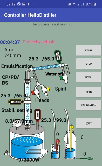
To set the required pressure, click the “Emulsification” inscription, after which the parameter settings shown in the figure below will appear.

To adjust, set the required pressure in the column and pressure delta.
Also set an emulsification power limit, typically around 2500 watts.
Set the parameters of the PID coefficients approximately as on the screen, i.e., Proportional 2-5, Integral 70-80, Differential – 0.
From the buttons, the process is launched as follows: press the “Select” button, use the “Left” or “Right” buttons to select the emulsification mode, here is a window:
![]()
Press the “Select” button again, information about the required emulsification pressure will appear.
![]()
By pressing the “Right” button, you can set the pressure delta.
![]()
Press the “Select” button, after which the emulsification screen appears.
Emulsification screens are similar to rectification screens, only instead of the letter “R”, the letter “E” is put, for example, instead of “Rect”, “Eect” will be written. The screenshots below are examples of screens.
![]()
![]()
![]()
![]()
Emulsification power limitation can be set by parameter
![]()
Pid coefficients can set in PID settings.
![]()
The description of the difference between the operation mode of emulsification from rectification is completed.
The setting mode of grain mash is intended for the automated process of digestion of grain raw materials. At the same time, automation of all stages is possible, with the exception of the stage of filling the raw material itself. The operation of the mixer, passage through temperature pauses and even automated feeding of yeast are supported.
The procedure for connecting equipment:
1) The temperature sensor No. 1 must be installed so that it measures the temperature of the mash.
2) The temperature sensor No. 2 must be installed so that it measures the temperature above the mash, that is, it warmed up to 80 degrees when it boils. It will signal a boiling jam.
3) Connect the heating elements of the mash vat or the heating elements of the steam generator to the outlet for the heating elements.
4) Connect the water supply valve to the cooling chiller or SWB jacket to the water supply valve.
5) If a mixer is used, connect the mixer control unit to the head valve control output.
6) If an automated yeast feed is used, then connect the yeast feed pump control to the NSC pump control output.
7) The level sensor of the receiving capacity can be installed on top of the mash. Its triggering will signal that the foam has gone.
To start the mode through the application, you need to select the menu items of the "Grain mash" or "Flour mash" or "Cooling and fermentation" buttons. All this is one and the same process, only the grain mash is performed completely, the cooking step is not performed in the flour mash, in cooling and fermentation mode only cooling and fermentation support is performed.

After that, the process screen will appear.

Before starting the process, you need to set the parameters you need, then press the "START" button, and the process will start.

To skip and manually go to the next step, press the SKIP button, for an emergency stop, the STOP button.
After all stages are completed, the system will switch to fermentation support mode, while the set temperature with a delta will be maintained, for example, the temperature above is 36.0 with a delta of 0.5 degrees. When the temperature rises, the mixer and cooling will turn on, when lowering, the heating in accordance with the settings PID controller.
The fermentation support mode can only be stopped manually using the button or by restarting the automation.
To select the jam setting mode from the controller buttons, press the “Select” button, use the “Left” or “Right” button to select the jam setting mode (cooking raw grain), here is the window:
![]()
either flour congestion mode
![]()
either cooling and fermentation
![]()
Then we press the “Select” button and the Temp Insert Grain Bill = 50.0 temperature entry window appears, at which crushed grain, or other unmalted raw materials, or malt will be poured when setting the mash without the need for prolonged cooking.
![]()
Using the “Up” button, you can increase the temperature, using the “Down” button, decrease it. Press the “Select” button to confirm and the following window will appear on the screen:
![]()
The inscription 23.1 / 50.0 means that the temperature in the mash vat is 23.1 out of the required 50.0 degrees. If desired, you can use the “Up” button to increase the temperature, and the “Down” button to decrease the temperature.
When the temperature in the mash reaches the desired temperature, a screen for inviting the introduction of a mound will appear on the screen:
![]()
It is necessary to fill in and press the “Down” button to confirm, after which it will heat up to the temperature of the preliminary pause, the window shown in the figure below will appear.
![]()
If desired, you can use the “Up” button to increase the temperature, and use the “Down” button to decrease the temperature. After reaching the pre-pause temperature (corresponds to the temperature of saccharification Temp Sacch Grain Bill) the following window will appear.
![]()
Why do we need a preliminary pause – you can add a little malt or enzymes with the mound, during this pause they will “work” a little and make the mash not so thick that it will facilitate cooking.
In this window, t = 63.3 means that the temperature in the mash 63.3, 2118W is the power at the heating element, 886 is the time in seconds that the pause ends. The total time of this pause is 900 seconds, that is 15 minutes.
At this stage, you can manually turn on the mixer with the “Up” button or turn it off with the “Down” button.
If the mode of setting flour congestion is selected, then the program immediately go to the saccharification stage if cereal, then at the end of this stage the program will go to the next – heating to the boiling point of the mash.
![]()
The end of heating to the boiling point is determined by the temperature sensor in the mash, or by temperature sensor No. 2, which must be installed above the mash so that it measures the temperature of the steam emanating from the mash.
If desired, you can use the “Up” button to increase the boiling point, and use the “Down” button to decrease the temperature. After reaching the boiling point, a mash cooking window will appear.
![]()
In this window, t=99.6 means that the temperature in the mash 99.6, 820W is the power supplied to the heating elements (defined by Power Cook Wash), 3429 is the end time of the cooking in seconds of the end of the pause. The default cooking time is 3600 seconds, i.e. 1 hour. If necessary, you can increase the cooking time using the “Up” button or decrease the “Down” button.
After cooking, the process of cooling to the malt making temperature (Temp Sacc Mash parameter)
![]()
During cooling, the water supply valve and mixer are periodically turned on at the same time. Periodically – because a constant supply of water leads to an increased flow rate. It is more efficient to supply water periodically. However, the mixer turns on in almost all operating modes. Stirrer operating mode set in brewing mode.
After cooling the mash to a saccharification temperature, a screen will prompt you to add malt (or enzymes).
![]()
Add malt to the mash and press the “Down” button.
This will be followed by an intensive mixing step for 15 minutes.
![]()
If necessary, you can increase the mixing time using the “Up” button or decrease the “Down” button.
After vigorous stirring, a transition to saccharification will occur.
![]()
In this window, t=61.3 means that the temperature in the mash is 61.3.
3581 Is the time in seconds the end of the saccharification. The total saccharification time is 3600 seconds, i.e. 1 hour. If necessary, you can increase the cooking time using the “Up” button or decrease the “Down” button.
After the end of saccharification, an automatic transition to the temperature of the initial yeast application will occur.
![]()
The initial introduction of yeast is some insurance against infection. At the same time, at a temperature of 40 degrees, a little yeast will be introduced by turning on the NSC pump for 5 seconds. If the pump is not connected, you can make yeast yourself.
Then the mash will be cooled to the temperature of the complete introduction of yeast (determined by the Temp Ferment Mash parameter)
![]()
If desired, you can use the “Up” button to increase the temperature, and use the “Down” button to decrease the temperature.
In this case, upon reaching the specified temperature, the remaining yeast will be introduced by turning on the NSC pump for 25 seconds. That is, the total volume of yeast must be selected so that they are introduced into the mash in about 30 seconds.
After the end of this stage, the system will switch to fermentation support mode.
The inscription t=38.3/36.0 means that the mash temperature is 38.3 degrees.
In this case, the stirrer is periodically turned on for more intensive fermentation.
Fermentation temperature and delta are set by parameters.
![]() and
and
![]()
![]()
If the temperature exceeds 36.0 degrees, the system will turn on the stirrer and cooling, and the window shown below will appear on the screen. The mixer and cooling will be performed until the temperature in the mash decreases below the fermentation temperature, taking into account the delta.
![]()
If the mash temperature is lower than the set temperature, heating will turn on. The window will take the following form:
![]()
If you do not need heating, you can either turn off the heating elements or set the PID coefficients of the heating elements to zero.
Also, the system will turn on cooling and mixing when the level sensor installed in the upper part of the mash is triggered. The triggering of the sensor in this case will mean that foam has gone.
Section Notes:
Note on automated yeast feed. You can use the same gear pump for NBC and yeast feed. Connect the pump in such a way as shown in the figure – a hose goes to the pump inlet from a container with fermented yeast, a hose goes to the mash from the pump outlet, and the hose is raised higher so that the yeast does not flow into the tank by gravity.

Note on the power supplied to the heating elements during the passage of temperature pauses.
In the process of cooking or until the desired temperature break is reached, power is supplied to the heating elements, according to PID control coefficients, the maximum power of the heating elements is limited by the parameter
Power Boil Wash / EMU = 3000
Therefore, before starting this mode, you it is necessary to set these parameters with the necessary values via the Set Param menu item.
The description of the setting mode of cereal mash is completed.
The simple steam distillation operation algorithm is based on the fact that distillation is performed, while the distillation power is automatically determined in such a way that the temperature set by the user is maintained in the reflux condenser taking into account the delta.
Let's consider this mode in more detail.
The procedure for connecting equipment.
1) The temperature sensor No. 1 must be installed in a cube in the vapor or liquid zone.
2) The temperature sensor No. 2 must be installed in the reflux condenser.
3) The temperature sensor No. 3 must be installed so that it measures the temperature at the outlet of the refrigerator or in the TCA (this is an emergency sensor, it is designed to complete work if the refrigerator ceases to cope with steam cooling (for example, if the water is turned off).
4) Install the level sensor of the receiving capacity at the required level in the receiving capacity.
5) Connect the valve for supplying water to the refrigerator, or for switching on the autonomous cooling system to the connector of the valve for supplying water.
6) If a mixer is used, connect the mixer control unit to the head valve control output.
Note: Do not connect the head selection valve and body selection valve; they are not used for distillation!
In the application, click on the “CM Distillation” menu item, after which the setup and process start screen appears.

Here we see all the necessary parameters, for example, the mode of operation of the mixer, the current process temperature, the temperature of the end of distillation. By clicking on the desired parameter, you can change it.
With this method of selection, it is recommended that the temperature in the cube of the end of distillation be set to no more than 92.0 degrees.
To start the process, press the "START" button, and the description of the current process will appear on the top line.

First, acceleration will be performed, the end of acceleration can be set either by the temperature of the cube or by the temperature of the reflux condenser by clicking on the corresponding inscription.
After overclocking, the distillation process will begin.

During distillation, you can set the temperature that must be maintained in the reflux condenser by clicking on it (in this case, 79.0). You can also set the temperature delta (in this case, at d 0.1)

To adjust the power supply,
click on the inscription PID,![]() then
set the PID controller parameters.
then
set the PID controller parameters.

The standard parameter values are Integral: 65-78, Proportional: 2-6, Differential: 0
To emergency stop the process, press the STOP button.
To start the process from the automation buttons, press the “Select” button, select the distillation mode with the “Left” or “Right” buttons, here is a window:
![]()
Confirm by pressing the “Select” button, a window for entering the distillation power will appear.
![]()
Using the “Up” and “Down” buttons, you can correct the power if necessary, then you need to press “Select” to confirm, the overclocking window will appear.
Default Overclocking End determined by the following parameter.
![]()
The image on the screen below means that the temperature of the thermometer at the inlet of the refrigerator (reflux condenser) is 31.7, when the temperature reaches 60.0 degrees, acceleration will end. The image above is the same, but the end of the acceleration is determined by the temperature of the cube. If necessary, the temperature of the end of acceleration can be reduced or increased by pressing the “Up” or “Down” button.
If the end of acceleration by temperature of the reflux condenser is configured, the controller display will take the following form:
![]()
Overclocking is possible manual transition to the next stage.
After overclocking is over, the program will switch to the operating mode shown in the figure below.
![]()
The image in the figure means that the temperature in the reflux condenser is now 78.6 degrees, the distillation process maintains a temperature of 79.0 degrees. If necessary, you can change the temperature of the end of the process by pressing the “Up” or “Down” button.
Power supply determined by the PID controller settings.
The standard parameter values are Integral: 65-78, Proportional: 2-6, Differential: 0
After the temperature in the cube reaches the set value, or the sensor in the receiving tank trips, the program will go into standby mode, while the heating is turned off.
![]()
And after the standby mode, in the end mode, while depending on the settings, it can emit a sound signal.
![]()
The description of the steam distillation mode is complete.
The setting of selection by temperature in the cube (“selection by Spur”) is based on the fact that the PWM selection smoothly changes depending on the temperature in the cube. The goal of all this action is a smooth selection, without stops, which (as considered by the adherents of this method) gives alcohol of the best quality. At the same time, nobody canceled the delta and stop in this controller, that is, if, during the selection by temperature in the cube, the stabilization temperature exceeds the delta, then the stop still occurs, after returning from the stop mode, the PWM will still be determined by the temperature in the cube, and not based on the settings for automatic PWM control.
So, the table, which may contain 15 temperature values and the corresponding PWM, is responsible for the selection by temperature in the cube. Between the values of the table, the selection is determined by linear interpolation.
To configure in the application, when adjusting the alcohol valve,
press the button
![]() .
.

After that, a table will appear in which you can indicate at what temperature in the cube what percentage of selection will be set. In the example below, for example:
1) to a temperature of 88 degrees in the cube, selection is not made
2) at a temperature of 88, the selection will be 68 percent and gradually decrease to a temperature in the cube of 92 to 25 percent.
3) at a temperature in the cube of 92, the selection will be 25 percent and then gradually decrease to a temperature of 95, at which the selection will be zero, that is, it will stop.

When setting up the selection table, take into account the temperature parameters for the end of alcohol selection and the end of rectification, which take precedence over the table. Therefore, they must also be checked and set to the desired values.
You can also configure the table to fill itself at each stop when the column is running. To do this, check the box "Auto-fill when stop."
The number of rows in the table will become negative. Negative values of the quantity is the sign of auto-filling.

The following will happen:
At rectification, the table is not used; at the beginning of rectification, the number of rows in the table is set to -1.
With each stop, a record is made in the table and the number of rows in the table decreases (increases modulo), that is, it becomes -2, -3, -4 and so on.
If you want to see the table, how it changed during the rectification process, be sure to click the “Read” button first, otherwise you will see the previous values
When viewing the table value in the process of rectification, it is advisable not to press the OK button so that the table is not overwritten by the values from the application memory.
After the end of the rectification process (surely before the start of a new rectification), the table should be looked at (the “Read” button should be started first), if it suits you, then change the negative value of the lines to the same positive value, if necessary, you can correct the temperature values. After that, confirm the table with the “OK” button and confirm the body selection parameters with the “OK” button to write the values to the controller.
To edit the table with buttons, you need to select the following parameter:
![]()
Here, the “Up” and “Down” buttons can be used to change the number of values used in the table.
The temperature dependence of the PWM table begins to be used in rectification, if the number of values is from 2 or more.
Moreover, if you set the "Count PWM" to less than zero, then when rectifying the PWM, the table is not used, but is automatically filled at each stop.
That is, according to the results of rectification, we will have a table of PWM dependence on temperature. To use it in work, the parameter "Count PWM" will need to be changed to the same, but positive value (if necessary, by editing the table).
To edit the table itself, press the “Select” button, the table value will appear on the screen, for example this:

This screen shows the value of the first temperature TempC (0) = 0 This is the very first value and can be left unchanged. In this case, the PWM value PWM (0) = -1% is negative, which means that temperature selection is not applied in this range.
To increase and decrease the temperature and PWM, press the “Up” Or “Down”, this will change the parameter on which the “*” sign stands.
To go to the next (previous) temperature value in the table, press to the “Right” (“Left”), the following value will appear, for example.


The value of the second temperature.
To memorize values, press the “Select” button.
Appendix 2. Possible non-critical malfunctions
1) If in the process of operation “mojibake/krakozyabry” appears on the screen (and this happens when there is interference from the valve or even just from the 220 (110) volt network), press the “Left” or “Right” key.
2) If the application connected to the controller successfully, but no parameters are changed from the application, then check to see if observer application.
Appendix 3. Basic Methods for Installing Temperature Sensors
In this section, we will look at how to properly install temperature sensors. Improper installation of the sensor can cause moisture to get inside it or display the temperature inaccurately.
So, the temperature sensor. It consists of a sleeve with a diameter of 5 mm (gray wire) or 6 mm (black wire), into which the wire is connected, a heat-shrink tube is put on the wire to protect it from excessive breakage of the wire. The benefit of this tube is just that. Therefore, if the sensor will not be installed outside the measured object and the sensor is not long enough, then it is better to cut this tube and instead stretch a silicone hose 4-5 cm long with an internal diameter of 5 mm and an external diameter of 8 mm. To make the hose easier to dress, it and the sleeve can be moistened with water. There is no need to wet with a 5mm sensor. It will look something like this:

Now, such a sensor can be installed in one of three ways.
The first method is installation in a hole with a diameter of 8.5-8.7 mm for a 6mm sensor and 7.5-8.7 mm for a 5mm sensor.
Something like this can be installed in a standard 1/4 plumbing fitting, which is drilled with an 8.5mm drill or a suitable fitting.


What are the advantages of this method – ease of removal of the sensor, the sensor is protected from the influence of the walls of the sleeve by a silicone tube, that is, the accuracy will be higher than if it touched the walls of the sleeve.
The disadvantages are the non-standard diameter of the hole. Typically, manufacturers provide sleeves with an inner diameter of 6 mm, and an external 8.
The second way to install the sensors is in a sleeve with an inner diameter of 6 mm and an outer diameter of about 8 mm.
Here's what this cartridge case looks like on equipment.

But how to install it, that is, the sensor slips into the sleeve, and the silicone tube is pulled onto the fitting:


What are the advantages of this method? Ease of installation and removal of the sensor, good tightness of the connection, standard dimensions of the hole for installation.
The disadvantages are the following: as a rule, a tube with an external diameter of 8 mm and an internal 6 is used for the sensor. The sensor is also 6 mm in diameter, so it can enter tight or not at all. For a 5mm sensor, this problem naturally does not exist.
To solve this problem, it is necessary to grind the sleeve from the inside with a round file in order to expand it to 6.1-6.2 mm. If you have the opportunity, you can drill a drill on a drilling machine. I do not recommend drilling with a drill, since it’s very easy to break the drill, then you are tormented by pulling out the wreckage.
Another drawback – the sensor touches the walls, which does not affect its readings in the best way. To solve this problem, it is necessary to install the sensor as deep as possible, but so that the tip of the sleeve does not touch any walls. It is also recommended to insulate the installation location of the sensor, for example, with foam rubber, wrapping it around the installation location.
The third installation method is to install it externally in a copper pocket.
Here is about such a pocket of copper, I soldered outside the column.
This is how the sensor is installed there:


What are the advantages of this method – ease of installation and removal of the sensor, absolute tightness of the connection, no need to drill a hole and install a fitting.
The disadvantages are as follows: the sensor touches the walls, which greatly affects the readings, you need to solder the pocket, moreover, from copper, and not from stainless steel.
Therefore, the sensor is usually installed this way when relative, not absolute, values are important, for example, temperature control at the start-stop in rectification.
It is highly desirable to insulate the installation location of the sensor, for example, with foam rubber, wrapping it around the installation location.
An overview of the basic sensor installation methods is complete.
Appendix 4 Tune PID Control Coefficients
In this section, we will consider setting the PID controller coefficients used to accurately set or maintain a given temperature. PID control is used in brewing, mash preparation, temperature control and other processes where precise temperature support is required. This is especially true when using SWB, because it is necessary to take into account the large inertia of the water jacket of a steam-water boiler.

PID
coefficients can be adjusted in the application.
To adjust the PID coefficients from the controller buttons, select the next item in the Set Param menu.
![]()
To change the “Window” PID knob, press the “Up” or “Down” button.
Here 2 is a proportional coefficient, 82 is an integral, 0 is a differential.
To change the coefficients, press the “Select” key, and then the screen shown in the figure below will appear.
To change a parameter value, press the “Up” or “Down” button; to go to the next parameter, press the ”Right” or “Left” button. For example, in the figure at the bottom left, the change in the integral component, on the right, is the differential component. To confirm the entry, press the “Select” button.
![]()
![]()
![]()
The coefficients can be either positive (not more than 127), negative (not less than -127) values, or zero.
The methodology for selecting the PID controller coefficients is beyond the scope of this manual, however, advice on selecting a proportional coefficient can be given as follows:
Subtract 2 from the temperature inertia of the system (for example, a SWB jacket), multiply by 8, multiply by a proportional coefficient, should give a value close to 1000 (this is 100% heating).
If you need to disable PID control, set the proportional factor from 125 to 127, and set the rest to zero or any positive value..
For reference, the degree of influence of the coefficients on the operation of the regulator is given.
a) The value of the proportional coefficient equal to 10 will give a change of 8% to the power of the rated power of the heating elements for each degree of difference between the current and the desired temperature in the system.
b) The value of the integral coefficient is a direct percentage increase in the integral component. That is, if it is 30, then it will change the power to a maximum of 30% of the power of the rated power of the heating elements, if 100, then 100% increase in power.
The integral component (not the coefficient, namely the component) accumulates with a given period (5 seconds by default) to its maximum of 100 degrees. That is, if the temperature differs from the required one by 1 degree, then the controller will switch to its maximum mode in terms of the integral component for a maximum of 100×5=500 seconds.
c) The value of the differential coefficient also gives a direct percentage increase, that is, a value of 10 will change the power by 10% of the nominal power of the heating elements, if the differential component of the temperature (acceleration of its change) is 1 degree.
Appendix 5. Additional windows (pages) displaying information.
Usually, only the first two information display windows are used in the work. These windows display the most relevant information for the current operating mode. However, there are additional windows that may be useful to you. To move between windows, use the ”Right” or “Left” button. When you try to switch to the first or last window or when switching to window 5, an audio signal is played.
Let's consider them in order.
Window number 3
![]()
Here, the controller ID is displayed in the first line, it is also possible to display system codes for the status of the Internet connection, as well as the time until the end of the connection session. The bottom line shows the IP address of the controller on the local network.
Window number 4
![]()
It displays the current temperature of all 5 possible temperature sensors and the pressure in the cube, in this case 13.5 mm.
Window number 5
![]()
This window shows the value of the liquid spill level sensors, the level in the receiving tank and the head level, respectively. The head sensor value is only shown if.
The current atmospheric pressure is also displayed here; it can be changed using the “Up” and “Down” buttons.
Window number 6
![]()
It displays the value of the zero per second detector (102), the power that should be supplied to the heating elements (340W), the actual power to the heating elements (2W), the value of the mains voltage at the controller input (243V), the current to the heating elements is 0.1A.
Window number 7
This window displays the system information of the power regulator.
![]()
The top line displays system information.
The bottom shows the distribution of power by phase. Power in the first phase is displayed in watts (166W). Power in the second and third phases is shown in volts (97V – the second phase and 97V – the third phase)
![]()
This is a rather interesting window, it is most useful in work. This shows the current state of the work process.
In some cases, a manual process change is allowed. In order to go to the next stage, for example, from the state of head selection to the state of body selection, click the “Up” button; to go to the previous stage, click the “Down” button.
I draw your attention to the fact that manual transition by stages is not always correct.
Unambiguously correct is the transition from work “for oneself” to the state of head selection during rectification, the transition from the state of head selection to the state of body selection in rectification. Other manual transitions may be incorrect, and their correct operation is guaranteed only if it is explicitly indicated in the instructions.
Window number 9
![]()
This is also a rather interesting window – the maximum temperature value for all sensors from the beginning of the current process is shown here.
For successful rectification, the column must be set up. The setting consists in selecting the operating capacity of the column and limiting the maximum selection of the column to the nominal value.
Installation of obor valves. The most popular selection valves at the moment are YWS1 and AR-HX-3.
Valves YWS1 they are connected through the fittings, and it is necessary to tighten them with a wrench or pliers all the way to or almost all the way, like in the photo.

At the same time, it is not necessary to install additional sealing elements, since the thread is tapered and itself tightens when tightened. But if necessary, you can use the tape FUM, for example.
It is recommended to place these valves with the coil up, while their service life is increased and the likelihood of alcohol getting there decreases.
Valves AR-HX-3 can be connected using a silicone hose that pulls on the valve as shown in the figure below.
In this case, the passport position of the valve, as in this photo, that is, thread up, fitting down.
However, in this position of the valve, alcohol can leak through the thread directly into the coil, so you need to cut a part of the thread with a file so that there are no grooves from the thread, even at the very beginning.
S
o,
approximately, as shown in the photo below

However, it is easier to install the valve “wrong”, that is, with the fitting up, thread down, as in the photo below. The pressure of the alcohol column during selection is not enough to push the valve stem spring, so this is very acceptable in our case.

Please note the selection limiter. When using this type of valve, the selection limiter is easiest to use a medical needle that is neatly cut with a file.


Consider first setting up a mechanical column selection restriction.
What is this for? The fact is that the characteristics of the column and valve selection units allow alcohol to be taken at a speed of up to 50 liters per hour. For example, a valve with a cross-section of 1 mm allows you to select at a speed of up to 15 l / h, and 2.5 mm up to 25 l / h. Naturally, household columns cannot give such a performance. And if you leave this selection, then automation will not be able to regulate it (see note to this section) Therefore, it is necessary to limit the maximum selection of the column by mechanical means.
How can this be done:
Clamp, tap on the tube from the selection unit
This is one of the easiest ways to mechanically limit selection.
It consists in the fact that a crane or clamp is placed on the connection pipe of the selection unit and the valve, which limits the maximum selection. In this case, after the selection is selected, the clamp or crane, if necessary, are fixed in the indicated position in some way, so as not to accidentally move them.
A medical needle or other stop in the tube from the sampling unit
This is also an easy and quick way to limit selection. A blue or green medical needle is inserted inside the tube from the bleed assembly to the valve. In this case, you must try so that the needle does not pierce the selection tube, for this the sharp end of the needle can be inserted into the valve fitting or tee. Instead of a needle, you can insert a cylinder from a material inert to alcohol into the tube (fluoroplastic, polypropylene, stainless steel) with a drilled hole with a diameter of 0.5-0.8 mm.
Here's something like in the photo, both valves are connected through a tee. To the tee from the selection unit is a tube into which a medical needle is inserted.
Throttle valve.
This method is a little more complicated, but also does not require much effort. A circle is cut out of a suitable material, for example, a fluoroplastic sheet, thin stainless steel, polypropylene, a beer can, a hole is made in the mug with a needle with a diameter of 0.5-0.8 mm
For example, here is a children's curd, it has a flat sidewall (the expiration date is printed on the sidewall, but it is easily washed off with cotton wool and alcohol).
A circle is about the same, in it, with a slight rotational movement of a medical needle or drill, drill a hole with a diameter of 0.5-0.9 mm.

The circle is installed in the valve.

Then the circle (which can already be called the proud name "throttle") is clamped by the fitting

Another way to limit selection is with a medical needle mounted on the tube in the receiving container, for example, as in the photo.

This method has one peculiarity – there should be no air jams in the tube from the valve to the sampling unit, otherwise the selection will be unstable or stop altogether. Air plugs will need to be driven out in some way.
And also there is another feature — the dependence of the selection on the height of the alcohol column above the needle (this method is based on one of the “manual” methods of adjusting the selection when the tube with the needle is raised or lowered to decrease or increase the selection speed).
Thus, it is necessary to make mechanical selection restriction in any of the ways.
After a mechanical sampling restriction is made, it is necessary to measure the sampling with the valve fully open.
In the application, at the time of the “Self” column operation, the valve calibration option is available.
To do this, click the "Calibration" button

Then a form for entering parameters will appear.
Here you need to choose which valve calibrates. If the sampling
restriction is applied differently for the valve, then each valve
must be calibrated separately, but if it is the same, then only one
valve can be calibrated. You can also change the calibration time,
but usually 30 seconds is enough. After selecting the valve and time,
substitute a measuring cup under the desired valve and press the
button![]() .
.
With this button, the selected valve will fully open and alcohol will
flow into the receiving tank, the button will start counting time
![]() .
.

At the end of the specified period, the valve closes and you need to enter the value that is in the measuring container, then enter the desired selection of either alcohol or heads, or both together, then press the OK button at the end of this procedure, the values will be transferred to the controller initial alcohol selection and head selection.
Without using the application, calibration is performed as described below.
During rectification, plug the valve into the water supply connector or make an adapter and plug it into a 220 volt outlet (or into another power source that is suitable for your valve model).
It is also possible during rectification during the selection of goals temporarily set the percentage of PWM goals 100%, the valve will also fully open.
After the valve has opened, take a beaker and measure how much alcohol is taken in 1 minute. After that, multiply the obtained value by 60 and get the volume of alcohol, which is selected in one hour.
For example, 20 ml of alcohol was taken out in one minute, which means 20 * 60 = 1200 ml of alcohol per hour.
So, we determined what selection we have without valves. After that, we decide for ourselves what kind of alcohol we want to receive. For example, we decided that our column could produce 700 ml of quality alcohol per hour. The maximum withdrawal with a fully open valve was 1200 ml.
Therefore, it is necessary to set the initial PWM of alcohol selection at (700/1200) * 100% = 58%. Set the parameter Beg% PWM Spirit to value 58.
Heads are usually selected at 10% of body selection, that is, the percentage of PWM goal selection parameter % PWM Head Rectif set to 58/10 = 6%.
Let's talk a little about determining the working capacity of the column
Directly to automation, this issue has no relation. For how to determine the operating capacity of the column, contact the manufacturer of the respective columns.
There are two main approaches.
Determining the power and speed of alcohol selection by pressure
With this approach, the column power and selection are set at parameters close to the choke.
First you need to set the power, obviously underestimated. For columns with a diameter of 30 mm, it is necessary to set the power of 500 watts, for columns of the DVN 38 mm – 900 watts, for columns of the DVN 50 – 1400 watts.
Having established low power, you need to let the system boil and work on it until the column temperature stabilizes. After that, it is necessary to measure the cubic pressure and again let the column run for 20-30 minutes. If a second measurement of bottoms pressure shows the same value, you can increase the power by 50-200 watts. Let the column run for 20-30 minutes after stabilization of temperatures and measure the bottoms again. If it does not change or grow over the next 20-30 minutes slightly, you can again increase power by 50-200 watts. and repeat the pair measurement again with an interval of 20-30 minutes. Sooner or later, at a certain power value, the data of pair measurements will differ significantly – re-measurement will be significantly larger than the first. This is a sign of choking. It is necessary to turn off the heating, wait for the cubic pressure to drop to zero, wait another 5-10 minutes. reduce the power by 30-50 watts and repeat the procedure of pairwise measurements in order to determine the maximum voltage that does not cause choking. If the selection of the head fraction does not exceed 50 ml / hour, this measurement can be combined with the procedure for selecting the head fraction. The working capacity of the column is considered to be found if, after 2-3 hours of work for itself without selection (or with a small selection of goals), the pressure in the cube will increase by no more than 2-3 mm Hg.
The selection in this case is determined by the input power, for example, if the power was 1500 watts, then the selection of alcohol should be carried out at a speed of 1500 ml / hour.
Determining the working power by pressure has long been used and gives acceptable results, however, some justifiably believe that working at such power and with such a selection gives a very mediocre product, so we also consider another way to determine the working power and speed of selection.
Determining the power and rate of alcohol selection by the parameters of the columns.
With this approach, work takes place at a pressure very distant from the choking pressure, generally speaking, they do not pay attention to pressure at all.
Many believe that with this approach, better alcohol is obtained.
However, with this approach, the rate of alcohol selection is 2-4 times lower than when working at facilities close to choking.
More details can be read here: http://forum.homedistiller.ru/index.php?topic=125908.0#msg12314657
Note to section: In principle, in the latest versions of the sketch there is a possibility set a very small PWM to the selection of goals, setting it to negative values, and sometimes you can even do without a mechanical restriction, but note that working in this mode is not normal for the column. Indeed, without mechanical limitation, extremely large selection (15-25 liters per hour) is activated for a short time. This selection removes the column from equilibrium, the fractions are redistributed over the nozzle, and undesirable fractions may enter the selection.
A little about the parameters that can be changed from the menu item Set Param of the controller.
To enter the parameter setting mode, press the “Select” button, use the ”Right” or “Left” button to select the Set Param menu item.
![]()
Press the “Select” button, then use the “Right” or “Left” buttons to select the desired setting
In addition, you can enter the parameter settings mode during operation by simply pressing the “Select” button two times.
If you are afraid of these values, then you may not read this section yet. Almost all parameters can be set directly when working in the corresponding modes.
The transition between the parameters is carried out using the “Right” or “Left” buttons.
It is possible to change the parameters by pressing the “Up” button to increase the value and “Down” to decrease. Confirm the parameters and save their values in non-volatile memory – the “Select” button.
Max term=20.0 Thermostat temperature (for the controller to work in thermostat mode)
![]()
Power HEAT=3000. Power of connected heating elements in watts
![]()
Power reg=500 The power that the controller should give to the power regulator (when the controller is in power regulator mode).
![]()
ParamUSART=0 Do I need to send values to the serial port (1-yes, 0-no)
![]()
If you set this parameter to 1, you can watch and save the operation logs using any serial port program, for example, HyperTerminal.
ParamWiFi=10 Wi-Fi connection options
![]() .
.
![]()
Temp 1 Distill=99.2 The temperature in the cube at which it is necessary to stop simple distillation (99.2)
![]()
Temp 2 Distill=96.4 The temperature in the cube at which it is necessary to stop the second (first fractional) simple distillation. Currently only used when starting Distill 2 mode using the buttons.
![]()
Temp 3 Distill=95.4 The temperature in the cube at which it is necessary to stop the third (second fractional) simple distillation. Currently only used when starting mode 3 Distill using the buttons.
![]()
Temp H-UP Rect (+ Cub, -Col)= 83.0 The temperature in the cube, at which the acceleration mode ends during rectification, the reflux condenser, the refrigerator are turned on, the power at which the rectification will be performed is set. Positive values mean that the first sensor (in the cube) will be used to determine the heating, negative that the second sensor (in the column).
![]()
![]()
Temp End Head Rectif= 85.4 The temperature in the cube at which the selection of goals ends and the selection of the body begins
![]()
PWM Head Rectif=20.00sec the value of the PWM period in which goals will be selected, in this case it is 20 seconds
![]()
![]()
If this value is set to negative, then it will mean the absolute value of the valve opening time in hundredths of a second, that is, that is, the value % PWM Head Rectif = -10 means opening a clan for 0.1 seconds.
PWM Heart Rectif=90.00sec the value of the PWM period at which the selection of SR will occur, in this case it is 90 seconds
![]()
Delta Heart Rectif=0.3 Delta selection of alcohol, When the stabilization temperature is exceeded + The Delta controller goes into stop mode and returns to the stabilization temperature.
![]()
Delta Return SR Rectif=0.0 Delta return alcohol selection, if this parameter is 0, then the return temperature is equal to the stabilization temperature, if it is different from zero, then the return temperature is equal to the stabilization temperature + this value.
![]()
Temp END Heart Rectif=96.5 The temperature in the cube at which the selection of CP stops and the selection of tails begins (in this case, 96.5 degrees Celsius)
![]()
Temp End Rectif=99.5 The temperature in the cube at which the selection of tails stops and the rectification ends.
![]()
min% PWM Sel SR=20% The minimum percentage below which the selection during rectification does not fall.
![]()
Edit Temp Stab Rectif=77.9 Editing the stabilization temperature of the column (for debugging or if suddenly it was determined incorrectly or not as the user wanted).
![]()
![]()
![]()
Temp Begin Dist (+ Def, -Cub)=60.0 Temperature in the reflux condenser (positive values), or in the cube (negative values) at which distillation starts, the refrigerator turns on, the power from the acceleration (maximum) is transferred to the distillation power
![]()
Temp Dist/EMU STM/PRESS=50.0 The temperature that must be maintained in the reflux condenser during distillation with a reflux condenser with steam extraction, or the pressure that must be maintained during emulsification.
![]()
Delta Dist/EMU STM/PRESS=0.1 Delta temperature or pressure delta plus or minus from which a temperature change is allowed with respect to the Temp Dist/EMU STM/PRESS parameter.
![]()
Temp Cube End STEAM=98.5 The temperature in the cube at which steam distillation stops.
![]()
BeepOnStateProcess=1 – squeak once when there is a transition between processes.
![]()
This parameter is responsible for the sound indication during the transition between the stages of the process. If it is set to 00000000, then it does not sound, at any other value, then when the transition to the next stage (for example, in the transition from head selection to body selection, in the transition from acceleration to operating mode), an audio signal is emitted.
Other modes of operation are determined by bits.
SECDNTLH
If L set to 1, then an audible warning will not be issued if the voltage in the network is less than necessary to maintain the given power.
If T set to 1, then a warning will not be issued or a single temperature sensor failure has occurred.
If N set to 1, then all sound signals will be muted.
If S set to 1, then the AEDT will not be disabled when the controller starts.
If E set to 1, then the AEDT will not be disabled when the process is completed normally.
If D set to 1, then in brewing the pump / mixer will not turn off when the wort temperature reaches 80 degrees, if 0, then when the temperature reaches 80 degrees the pump will not turn on.
Bits C and H are not used
Note: The parameter disables only sound signals; on the screen, in any case, a corresponding message will be displayed.
Beep end=1 – periodically make a sound when the process ends.
![]()
Beep key=1 – emit a sound when pressing the buttons.
![]()
Power Cook Wash=820W Power at which grain raw materials will be digested. It is selected individually for the mash-up in such a way that the mash boils, and there is no excessive energy consumption.
![]()
Amendment ds18b20 – Switch to the mode for entering corrections to temperature sensors.
![]()
Conduct SR=2 parameter that is responsible for the end of the selection process
![]()
Volt valve=300 What voltage to apply to the valves, to protect them from overheating
![]()
Use Avtonom Cooling=0, if it is set to 1, the phase control is disabled for the water supply valve, for the selection valves, the control remains the same defined parameter Volt valve.
![]()
Beg% PWM Spirit=20% initial percentage of PWM body selection, which is set automatically immediately after the selection of goals.
![]()
Auto - PWM=10%, by how many percent it is necessary to reduce PWM at a stop.
![]()
Auto + PWM= 0%, which answers how many percent you need to increase the PWM in the absence of a long stop.
![]()
Time Auto + PWM = 600 the time during which it is determined that there is no stop for too long.
![]()
Power Boil Wash/EMU=3000W The power at which the cereals will be boiled and brought to a boil (it can be less than the power of the heating elements, because at full power there can be flaring), as well as the maximum power supplied to the heating elements in brewing. This parameter is also used to limit the maximum power during emulsification.
![]()
Alarm press MPX5010=25.0mm The parameter that is responsible for the pressure alarm. If the parameter is nonzero, then when it is exceeded, a warning is issued first, and then an error with the process stopping.
![]()
Time reStab (+/-) Column = 3600. This parameter is responsible for the automatic exit of the column from the "stop" mode. By default, it is 3600 seconds (i.e. an hour). If the column is in the “stop” mode for more than the seconds specified in this parameter, then the stabilization temperature of the column is taken as the current temperature in the column. Usually a long “stop” time occurs when atmospheric pressure changes. If the parameter is set to negative, for example, Time reStab (+/-) Column = -3600, then if the column is in the stop for more than the specified time (in this case 3600 seconds, that is, one hour), then it switches to the selection of tails. If this parameter is set to zero (Time reStab (+/-) Column = 0), then the automatic exit from the “stop” is disabled.
![]()
Temp Sacch Mash = 60.0 This parameter means what temperature to maintain during saccharification of the mash.
![]()
Temp Insert Grain Bill = 60.0 This parameter means at what temperature malt or crushed grain will be added.
![]()
Temp Ferment Mash = 36.0 This parameter means what maximum temperature to maintain while supporting mash fermentation, and also determines the temperature of yeast application.
![]()
Power corr ASC712 = 2. This parameter is responsible for adjusting the output power based on the current sensor. Possible values: 0 – correction is not used, 1 – correction is not used, but the actual power is displayed on third page of the controller, 2 – current correction is used.
![]()
![]()
min Pres CWC = 13.0 This parameter is responsible for the pressure on the basis of which decide on the rate of distillation of the NSC. For example, the picture says min Pres CWC = 13.0 + 2.5 = 15.5
![]()
this means that at a pressure of less than 13.5 the system will increase the supply of mash, in the interval from 13.5 to 16.0 the mash supply will not automatically change, at a pressure above 16.0 the system will stop the flow and wait for the pressure to drop. If the minimum pressure is not set (equal to 0), then auto-adjustment of the supply of mash will not be performed. It makes sense to set the zero value if you are working without a pressure sensor.
dlt Press CWC = 2.5 this parameter is responsible for the range in which automatic feed control will not be performed. In the figure, this is a range from 13.5 to 16.0.
![]()
If the delta is not set (equal to 0), then an automatic increase in the feed rate will not be performed, however, the system will stop if the pressure is exceeded.
time Pressure CWC= 180. This parameter is responsible for the period during which it will be accepted decision to increase or decrease the feed rate. For example, the figure shows that this decision will be made once every 180 seconds.
![]()
Temp strait CWC = 80.0
![]()
If the grains(draff) temperature has dropped below this temperature (in this case below 80.0 degrees), then the system stops feeding and waits for the grains temperature to exceed this temperature increased by 0.5 degrees (in this case 80.5 degrees), after which the mash supply continues. but its feed rate is halved. If in 10 minutes there has not been a return to the desired temperature, then the NSC distillation process is completed.
Temp UP CWC= 93.0
The temperature at which will be regulated filing mash.
![]()
Temp End CWC= 98.0. This is the temperature at which the NSC process will be completed at the end of the filing.
![]()
Contr Pump CWC = 00000001. This parameter indicates how it will be performed.
NSC pump control.
![]()
The following values are available:
1 – the pump turns on high and turns off low, control is performed according to Bresenham. This value is used when controlling, for example, a gear pump, emergency shutdown through the NSC pump connector is not used.
9 – the pump turns on high and turns off low, control is performed according to Bresenham. This value is used when controlling, for example, a gear pump, emergency shutdown through the NSC pump connector is performed when the contacts open.
17 – the pump turns on high and off low, control is performed according to Bresenham. This value is used when controlling, for example, a gear pump, emergency shutdown through the NSC pump connector is performed when the contacts open.
0 – the pump turns on low and off high, control is performed according to Bresenham. This value is used when third-party pump control drivers are controlled, emergency shutdown through the NSC pump connector is not used.
8 – the pump turns on low and off high, control is performed according to Bresenham. This value is used when third-party pump control drivers are controlled, emergency shutdown through the NSC pump connector is performed when the contacts open.
16 – the pump turns on low and off high, control is performed according to Bresenham. This value is used when third-party pump control drivers are controlled, emergency shutdown through the NSC pump connector is performed when the contacts are closed.
5 – The pump is controlled by the PWM PWM period is one second, 125 pulses are supplied per second, this value is used when pumps having a similar control circuit are used, for example, pumps from Igor223, sold on the website http://samogon-i-vodka.ru/catalog/1240/, emergency shutdown through the NSC pump connector is not used.
13 – The pump is controlled by PWM, emergency shutdown through the NSC pump connector is performed when the contacts open.
21 – The pump is controlled by PWM, emergency shutdown through the NSC pump connector is performed when the contacts are closed.
% selec Tsarga Paster (+/-) = 6%. This parameter is responsible for the percentage of goals scored through the drawer.
![]() pasteurization
(that is, in fact, the selection of goals through the valve heads
during the selection of the body).
pasteurization
(that is, in fact, the selection of goals through the valve heads
during the selection of the body).
Positive and negative values are possible.
Positive values mean that the selection will be made as a percentage of the main selection of goals. That is, if you put a value of 10, and the selection of goals costs 10%, then the selection through the pasteurization team will be 1%.
If the value is negative, then each unit means opening the head-selection valve for 1/100 of a second every 10 seconds (period of operation of the head-valve).
If you set 0, then the selection of goals through the pasteurization drawer will not be made.
Temp Alarm VENT= 65.0. This parameter answers at what temperature the TCA accident will be detected at the third sensor.

Voltage = 220V. This parameter allows you to set the mains voltage manually, which may be necessary to correctly determine the power of the heating element in case of voltage drops in the network.

